D5252T V70/S70 850
The D5252T engine is a 2.5-liter inline-five-cylinder turbo diesel engine developed by Volkswagen and used by Volvo in several models, including the Volvo 850, S70, and V70 during the mid to late 1990s. It features a direct injection system and is turbocharged with an intercooler. Producing around 140 horsepower and 290 Nm (214 lb-ft) of torque, the D5252T offers solid mid-range performance and good fuel economy for its era. Though somewhat noisy compared to modern diesels, it was appreciated for its durability and long lifespan when properly maintained.
- INJECTORS
- SERVICE ITEMS
- TIMING PARTS AND TOOLS
- BOSCH VP36 EDC INJECTION PUMP
- INJECTION PUMP ELECTRICAL TESTING
- TIMING BELT
- AUXILIARY BELT
- OIL CHANGE
- V70/S70 MSA 15.7 M56 CLUTCH
- 850 CLUTCH
- PCV VALVE
- FUEL LINES
- Starter Motor
- Vacuum Pump
INJECTORS
Torque Specs
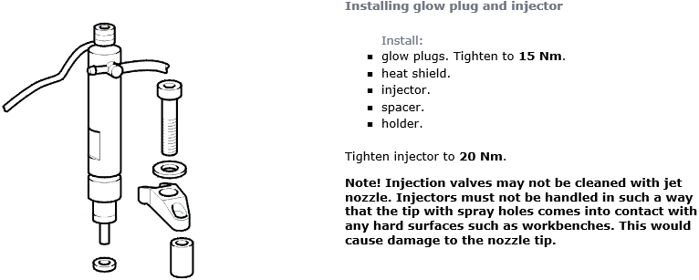
Injector 4 (Needle Lift Sensor)
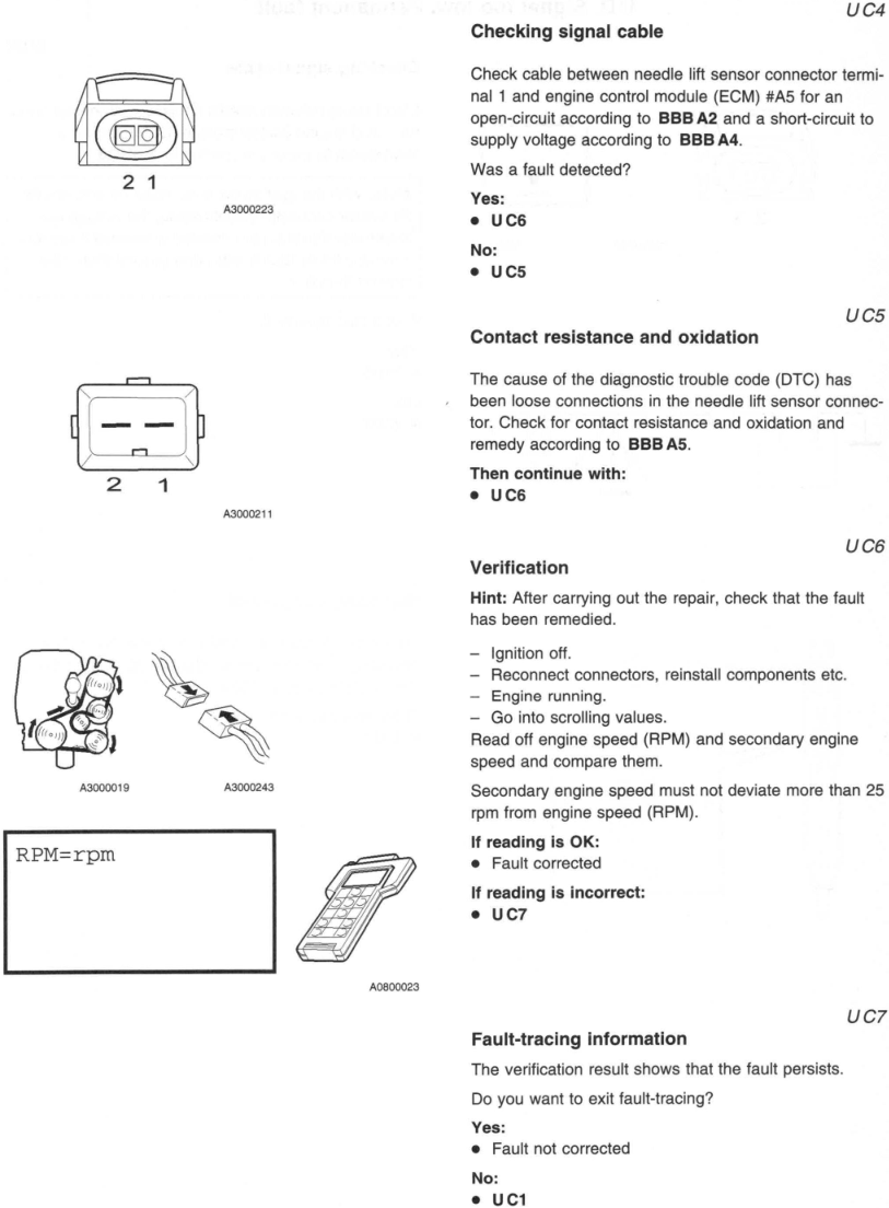
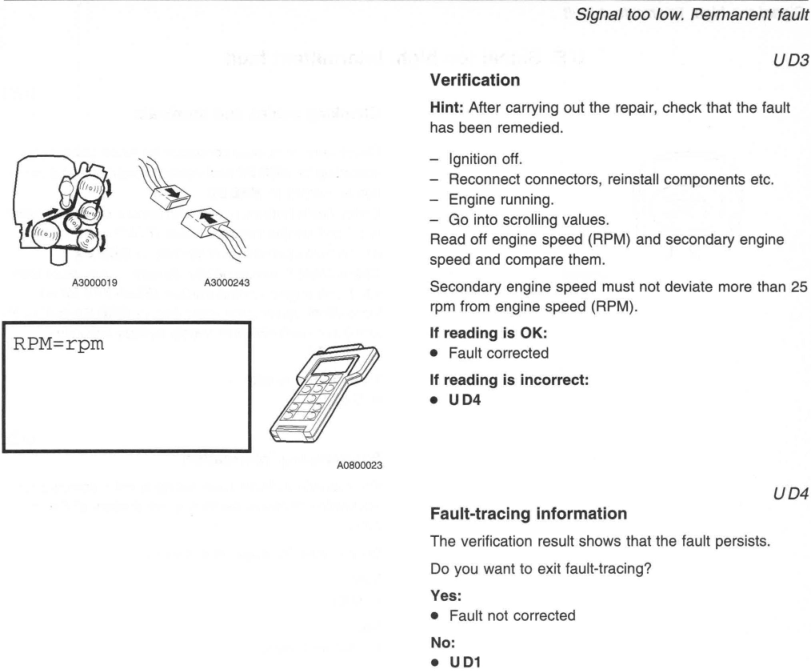
Engine speed SEC (RPM) and crankshaft position, from the engine speed (RPM) sensor and needle lift sensor.
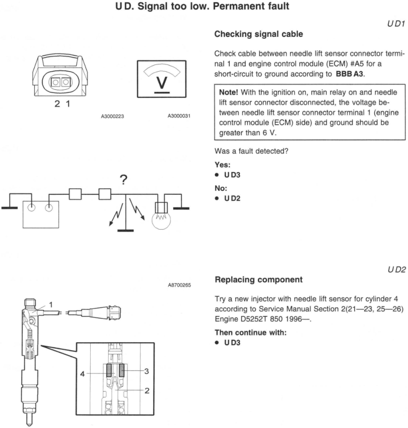
Design and function
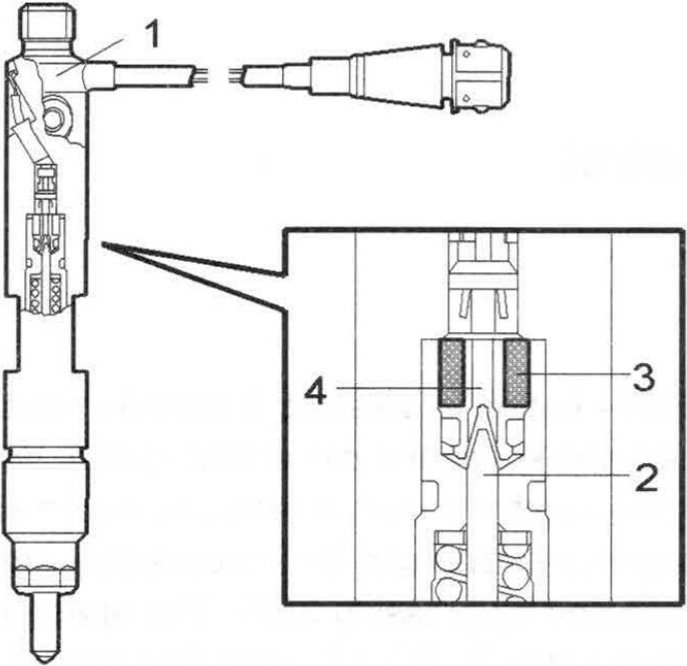
— Needle lift sensor (1)
— Needle (2)
— Magnet coil (3)
— Magnetic core (4)
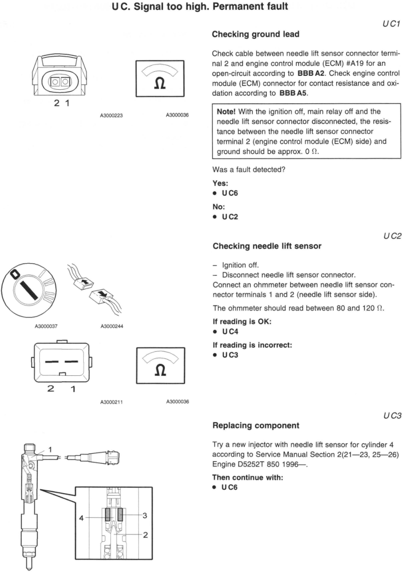
The needle lift sensor is located in the injector for cylinder four. The value at this injector must represent all the injectors in the engine. The needle lift sensor transmits signal to the engine control module (ECM) when injection starts.
By comparing this signal with the signal from the engine speed (RPM) sensor the engine control module (ECM) can calculate the difference between calculated and actual injection timing and make necessary corrections.
If the signal which represents the movement of the needle is missing, the quantity of fuel injected is limited and injection timing is overridden. If at the same time there is a fault in the engine speed (RPM) sensor the engine will stop.
The needle lift sensor consists of a magnet coil wound around a magnetic core. The coil has a DC voltage supply, regulated so that current remains constant, irrespective of temperature variations. When injection starts the magnetic core (connected to the needle) moves upward disturbing the magnetic field. This causes a change in voltage in the power supply. The engine control module (ECM) determines when injection starts by registering this change in voltage.
EFI-711 Needle lift sensor, signal
Condition
A diagnostic trouble code (DTC) is stored if battery volt age is greater than 9.14 V and the signal from the needle lift sensor is greater than 0.60 V or below 0.10 V.
Substitute value
— Only initial boost pressure permitted
— EGR control is disabled
Possible source
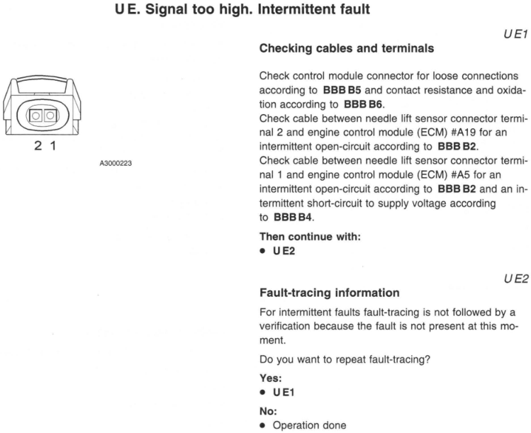
Signal too high:
Open-circuit in signal cable or ground lead
Short-circuit to battery voltage in signal
Contact resistance in terminals
— Defective needle lift sensor
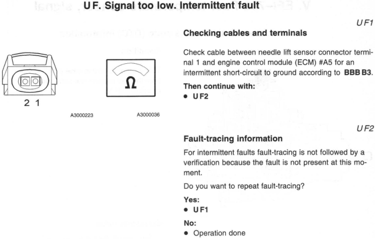
Signal too low:
— Short-circuit to ground in signal cable
— Defective needle lift sensor
Fault symptom(s)
— Poor acceleration, engine sluggish
— Engine knocks when idling
How to install replacement TDI nozzles
Introduction
This article shows installation of new TDI fuel injector nozzles for all 1996-2003 Volkswagen TDI or Audi TDI engines (non pumpe duse)
Due to mileage and use, the tip of the fuel injector (the nozzle) will wear out and requires replacement to restore the injector's spray pattern to like new condition. The benefits are both more power and economy. If you think there is a problem due to bad fuel or buildup, you can try running a can of diesel purge through the fuel system. Buildup due to low quality fuel and normal wear will disturb the spray pattern and cause uneven combustion and temperatures. If the problem is wear, the only solution is nozzle replacement. You can also replace the nozzles with larger nozzles with a larger opening to make more power (and possibly more smoke) by injecting more fuel. It's unlikely for damage to occur from only worn OEM nozzles but replacing the nozzles will restore your lost fuel economy, power, make less smoke, and give the car a smoother idle. For more information on nozzle selection and technical details, see 1000q: nozzle selection FAQ and 1000q: basic power modifications.
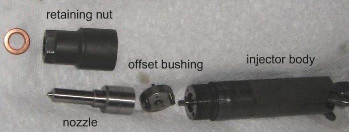
Although this is an easy job, cleanliness is extremely important! The nozzle holes are very small and particles can damage and clog the injectors. While the injector tips withstand thousands of psi of combustion in the engine, having dirt stuck behind the tiny nozzle orifice is like squeezing out an apple sized kidney stone - you're at risk of a blowout. Below is a slightly larger than life size picture of an old nozzle next to a caliper. The entire nozzle tip is less than 4mm and you can see the enlargement of a new nozzle tip with a red arrow pointing to the orifice measuring .184 millimeters (mm). You want the injector internals and area around the injector holes to be very clean. This is an easy job but please follow the directions below! Counterholding is suggested on some parts (like the fuel hard lines) because not counterholding could result in damage! The injector holding forks have been known to break due to overtorquing as well so make sure you have an accurate torque wrench. For more basic mechanic's tips, see 1000q: basic mechanic's tips.


TDI nozzle Parts
10, 14, 13, 15mm wrenches and sockets.
17mm open faced wrench or 17mm flare nut wrench or VW special tool #3035, equivalent tool from metalnerd
torque wrench
brake cleaner spray
PB Blaster
lots of paper towels and rubber/vinyl gloves
vise
pliers
screwdriver
slide hammer to remove the injector (Optional) available from metalnerd tools (halfway down the page) or you can make your own (see below)
vacuum cleaner (Optional)
new nozzles (4 total) available from : kermaTDI.com, JSperformance (Canada)
new copper injector washers VW# 046 130 219 A (4 total, included with most nozzle sales but always make sure)
Replacement procedure
Summary: Remove the glow plug harness, move the fuel lines to the side, and unbolt the injector holders. Pull out the injectors, remove the old nozzles, put the new nozzles on, replace as necessary.
Detailed procedure: First let the engine cool down so that is not hot to the touch and park/secure the car. Make sure the car is secure and off before doing anything else. Make sure there is adequate ventilation because some diesel fuel and vapors will be leaked and observe all safety practices cautioned in your factory service manual when working on the engine. Although diesel vapors aren't as flammable from an open flame at room temp/pressure as gasoline vapors (an example of this is shown in the video below at the 1:00 minute mark, don't try to replicate the experiment yourself), you still want to observe all safety practices in your factory service manual pertaining to this procedure and evacuate any fuel fumes that are present. Keep all sources of ignition away from spilled fuel and/or vapors. Diesel fuel will also melt rubber coolant lines or driveway asphalt.
Open the hood and remove the top plastic engine cover (3 x 10mm nuts).
Cleanliness is very important in this job! Put on rubber or vinyl gloves to protect your hands against the fuel. Once the engine is cool, wipe down any oil or dirt away from the front of the cylinder head, fuel injectors, and glow plugs. Then wad paper towels around the base to collect excess fluid and spray the metal head around the fuel injectors and glow plugs with cleaner. Also clean the flare nuts at the end of the fuel lines and wipe down the fuel lines. Clean it again. Repeat as necessary. You can also use a vacuum cleaner to help clean the area but I find that carb cleaner and compressed air is better at loosening stuck particles.
The fuel injector metal pressure lines will loosen much more easily if you put a few drops of PB Blaster, liquid wrench, or a similar penetrating lubricant around the threads. Also apply to the fuel line side of the injector pump union fitting only to help prevent loosening the unions.
Remove the black glow plug harness (outlined in red below). Each of the 4 plugs should pull straight off easily. Place to the side and clean as necessary. You can also remove it later if you don't have enough clearance.
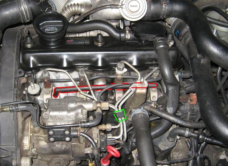
Use a screwdriver to remove the black plastic clips (outlined in green above) holding the pairs of metal fuel lines together. Some cars have a metal clip.
Remove the fuel pressure lines from the injector tops. Note: you probably don't have to counterhold the injector body during fuel line removal since the injectors will be frozen with buildup but it is suggested to counterhold them for reinstallation or if the injectors are loose. To counterhold, use a 15mm open wrench against the flat part of the injector body to prevent movement while you use a 17mm wrench to remove the nut at the fuel line. The tightening torque is only 15 ft-lbs but for some reason, the forks on the injector holding bracket have broken with only a little excess force. It's tempting to not counterhold but it couldn't hurt. The forks can also break when it's 13mm bolt is torqued to greater than 15 ft-lbs, so take note for reinstallation!
If you don't have a torque wrench that will fit on the nuts, use a permanent marker to make an index mark on the nuts before loosening them. Make each mark in the same direction (like pointing up or down) so that you have a better idea of how much to tighten the nuts during installation.
Now loosen the fuel lines at the lines at the injection pump (17mm nut), just enough to swivel the fuel hard lines out of the way as necessary. I suggest using a 14mm wrench to counterhold the union at the lines at the injection pump end (so the union at the injection pump doesn't spin in the pump).
Caution: the moved fuel lines may interfere with the hood so avoid closing the hood if there is a clearance issue.
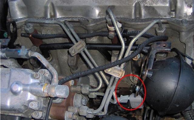
You should now have plenty of room to remove the needle lift sensor's wire coming from injector #3. It's the only injector with the wire coming out of the top. Pinch in the metal or plastic clip at the plug (circled in red below) and carefully wiggle the plug off. Pictured are 3rd generation and ALH engines, they are similar except the plug is in a slightly different location and uses a different connector.

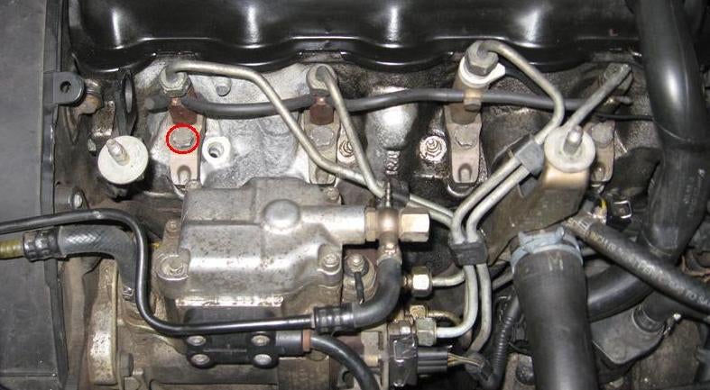
Remove the 4 injector holders (the metal fork holding the injector) and place to the side. There is 1 conical washer on each injector holder and they are each held by 1 x 13mm bolt (circled in red below). In the below picture I removed a glow plug to do a compression test and hadn't yet cleaned the other spots or removed the fuel lines.
Now you can remove the injector bodies. They'll be stuck so below are some tips.
Injector removal tips
The injectors are pulled straight out since there are no threads, there is nothing but carbon buildup holding them in place. Most people find that the injectors will wiggle out, some people find that they are completely frozen in place. To help loosen the injectors, put a drop of PB Blaster penetrating lubricant around each injector hole when you start the project. This will give the PB Blaster time to penetrate the area and should break up the buildup. After you start to wiggle the injector and get motion, add another drop to lubricate the hole.
Caution: here's what NOT to do:
- If you leave the injectors out of the car and dry for more than a day or two, keep them immersed in diesel or diesel fuel additive. Injectors have been known to seize when left dry for a week.
- Don't pull on the fuel lines or return line nipples at the top with anything more than a gentle touch.
- Try to avoid spinning the injector body counter-clockwise if it's seized. This can release the retaining nut while it's still stuck in the cylinder head and pop out the injector internals. This will make life difficult. If this happens, you can take apart another injector to see how it should be put back together.
- Don't heat the injector or nozzles with a torch since this could damage them. You can torch a rusted bolt on the muffler but don't use it on the sensitive needles and springs of the injector or nozzle because they could get messed up.
Wrench method
First try using a 15mm open faced wrench on the flat part of the metal injector body to wiggle them back and forth. Do NOT pull on the fuel lines or nipples with anything more than a gentle touch. Try to make the first "break" clockwise or wiggle it back and forth so that it doesn't loosen the retaining nut before you loosen the whole assembly. If this happens, the injector internals will pop out and the injectors will not make you happy. As they start to move, put another drop of PB Blaster at the base of the injector body to lubricate the hole.
Slide hammer method
You can either buy, rent, or make your own slide hammer to carefully pull them out. A slide hammer is a weighted rod that lets you apply force on the injector along the axis of the slide hammer. They are available from metalnerd tools (halfway down the page) or you can make your own. To make your own, find or rent a slide hammer and attach the end to the injector threads. The threads are 14mm x 1.5mm pitch. Some hardware coupling nuts are 2mm pitch. A 3lb weight should work, a 5lb weight may be needed for extreme cases. I took a damaged fuel pressure line and bent it straight to make a puller, pictured below. It attaches to the top of the injector. A slide hammer attaches the same way.

Once you get the injectors out:
Place all 4 injectors a fresh and clean surface like clean paper towels. Lint free towels would be best.
Below is a picture of the head after injector removal. Note that the hole is not threaded - the injector fork holds the injector in place. You can see buildup in the #2 injector seating surface. Clean the area around the injector holes and seating surfaces. This is very important because excess dirt can cause a compression leak if not cleaned! I suggest using a soft swab moistened with carb cleaner to wet the area first. If you use a q-tip, tie a string around the end because it's small enough to fall into the hole and cause a bad day. To avoid getting fluid inside the injector hole (since it leads to the cylinder and could cause hydrolock), spray fluid directly on the q-tip instead of on the hole. This is a type of serious engine damage resulting from letting too much non-compressible liquid inside the cylinder. Carb cleaner should evaporate if it gets into the hole but I'd still rather not have it filled with fluid. I do not suggest using metal objects to clean the area since this can cause a scratch to the sealing surfaces and leak. I would avoid using a pick or screwdriver since the head is aluminum, a soft metal. Also do not use compressed air since this will blow particles all over the freshly cleaned surfaces and onto the exposed fuel lines. A vacuum cleaner works well here as well. If a small piece of built up soot falls into the hole it will burn up when you start the engine so don't freak out.

The sealing washer will be stuck on to the injector with soot. I suggest using pliers and turning the washer a 1/4 turn with a light pressure. This will break the carbon buildup and the seal. Don't go near the retaining nut's sealing surface to avoid scratching it (marked with a red line below). Don't use a screwdriver or pick to remove the washer because this can scratch the surface! Clean the exterior of the injector as much as possible.
If the copper washer is not there, it's probably stuck to the cylinder head! Remove it to prevent any compression leaks.

Use a vise to hold the flat part of the injector body - put a paper towel around the base in case fuel leaks out. (It also keeps the injector clean since my vise was dirty). If you are thinking of just holding it with pliers you are asking for a dropped/dirty/damaged nozzle. All four of my injectors also needed a breaker bar to loosen them, so some sort of vise is a must here!
Use a 15mm deep socket or wrench to loosen the retaining nut/cap. Because it will be so tight, I recommend using a 6 point deep socket/wrench instead of a 12 point socket/wrench or an open faced wrench. This will minimize the chances of the wrench slipping and scratching the retaining nut. Remember that a scratch on the sealing surfaces can cause a compression leak! See 1000q: mechanic's tips for more useful tips.
Remove the retaining nut/cap and clean the inside and outside of the nut/cap thoroughly. Also clean the outside of the injector body. Avoid turning it upside down since the metal bushing can fall out. There is a large metal disk with a bushing in the center. This can easily blow away if you wipe or use compressed air, so be careful! If it lifts up, it will only seat 1 way, and the nozzle will also only seat 1 way due to the offset pins.

Repeat for all 4 injectors. As you handle the nozzles, keep them pointed down so that the needle inside doesn't fall out.
Put on the new nozzles, taking care not to touch the tip with anything that will leave a lot of lint or could scratch the metal. Take care not to drop the tip or hit it against anything. Again, the nozzle will only fit 1 way, the 2 pins on the injector are offset so that the 3rd hole of the nozzle aligns with the 3rd hole on the injector body. Also don't try to disassemble the nozzle or injector body - they're not toys and you are better off keeping them clean and intact!
When you slip the retaining nut on, go slow to avoid banging the tip. There is a preloaded spring inside so the nozzle will not be completely seated flat. When you tighten the nut it will seat and some diesel fuel may come out the fuel nipples at the bottom. Note: there is no torque setting, 33 ft-lbs has been mentioned but the correct way to tighten the retaining nut is to turn until wrench tight, then turn another 30 degrees. This should be be than 33 ft-lbs. Undertorquing the retaining nut/cap causes leaks!
You can drop the sealing washer into the injector hole and carefully center it with a thin screwdriver or use a very thin touch of grease to hold the washer on the bottom of the retaining nut as you lower it in. Make sure that the copper washer is fully seated, aftermarket washers have been known to not fully seat and cause compression leaks. Carefully slip the injectors in, replace the injector holders, bolt, and washer. CAUTION - the conical washer for the 13mm bolt is directional! The curved side points down. If you put the curved side up, it will crack the washer.

Remember, counterhold the injector body with a 15mm wrench while you tighten the fuel lines because the injector holding forks are weak and have been known to crack!
Replace all 4 fuel lines, 3rd injector needle lift sensor plug, and glow plug harness.
Torque settings:
- If you missed it, the fuel injector retaining nozzle should be torqued to wrench tight and then another 30-45 degrees. 33 ft lbs has been mentioned but this oftentimes results in leaks. If you have an accurate torque wrench, 33 ft lbs plus a 30-45 degree turn can also be used.
- fuel line flare nuts: 18 ft-lbs - remember to counterhold the injector body with a 15mm wrench. CAUTION: don't overtighten the flare nuts because you could distort them and cause a leak. Tight is good, overtightened is bad.
- If the other end of the fuel line (the union) in the injection pump loosened and spun, torque the union to 33 ft-lbs.
- forked injector holder bolt: 15 ft-lbs - WARNING: the injector holder forks have been known to break off when torqued too much, do not over tighten!
- CAUTION - the conical washer for the 13mm bolt points down. If you put it face up it will crack.
Starting the car - it might not start without priming
You are now ready to start the car. It may take a while of cranking to start the engine. Try to crank for no longer than 30 seconds followed by at least 30 seconds of rest. As long as you did not empty the fuel filter or injection pump, there will still be some fuel in the system and the car should start with some cranking. If the car still doesn't want to start, slightly loosen one of the 17mm fuel line nuts at the fuel injector, wrap a rag around it, and crank the engine twice. It should be wet with fuel. Retighten the nut and crank the engine again.
Check for any fuel leaks or odors. Inspect the area around the base of the injectors for leaks or bubbles. Also inspect for any wet areas that would indicate a leak. Drive the car for about 500 miles or so to let the new nozzles settle in. If you also have a chip, you should ideally have a new chip made that takes into account the larger nozzles.
You may want to adjust fueling through injection quantity adaptation, see 1000q: injection quantity adjustment and the section "Testing and changing IQ with software adaptation" for more details and screenshots. Here is a summary: Drive the car and let it warm up to normal operating temperature. While idling, open VCDS, login with code "12233", adaptation, block 1. Adjust adaptation value higher or lower to adjust IQ to the 3.0-5.0 mg/R range. Hit "save" when you are satisfied. When you are done, exit and then go back to make sure the values you wanted are still there.
Do you know something that should be added or corrected in this article? Post your comments in the myturbodiesel.com forums
For reference, here is a parts listing for the ALH TDI fuel injector system:

SERVICE ITEMS
Volvo Special Tools
| Tool | Brand | Part Number(s) | Price | Link |
| Retainer for Crankshaft pulley Tool | Volvo | 9995645 | N/A | This part is discontinued. |
| Timing belt tensioner Tool | Volvo | 9995649 | N/A | This part is discontinued. |
| Camshaft Counterhold | Volvo | 9995644 | N/A | This part is discontinued. |
| Injection Pump Timing kit | Laser | 6566 | £233.11 (30/09/23) |
LINK |
| Timing Tool kit | NEILSEN | CT0521 | £23.64 (30/09/23) |
LINK |
| Injection Pump Timing kit | NEILSEN | CT4077 | £24.95 (30/09/23) |
LINK |
Oil Change
| Tool/Part | Brand | Part number(s) | Price | Link |
| Oil Filter | VOLVO | 9125224 | £18.15 (30/09/23) | LINK |
| Oil Filter | MANN | W 1130/3 | £ 11,02 (30/09/23) | LINK |
| Oil Filter | MAHLE | OC 214 | £ 11,34 (30/09/23) | LINK |
| Oil Filter | BOSCH | 0 451 203 223 | £ 11,17 (30/09/23) | LINK |
| Oil Filter Tool | BSG | 1039-108-15 | £11.00 (30/09/23) | LINK |
| OIL (6 Liters Cap.) | MANNOL | 20L Fully Synthetic Engine Oil EXTREME 5W-40 SN/CH-4 A3/B4 VW 502/505 |
£69.89 (30/09/23) | LINK |
| Sump plug washer | VOLVO | 977751 | 0,56 EUR (30/09/23) | LINK |
| Sump plug washer | GENERIC | OE977751-7 (100 of them) | £14.80 (30/09/23) | LINK |
Fuel Filter
| Tool/Part | Brand | Part number(s) | Price | Link |
| Fuel Filter | VOLVO | (9454805) (31262351) (1270529) | £14.88 (30/09/23) | LINK |
| Fuel Filter | MAHLE | KC 69 | £ 15,76 (30/09/23) | LINK |
| Fuel Filter | BOSCH | 1 457 434 184 | £ 19,62 (30/09/23) | LINK |
| Fuel Filter | MANN | WK 845/1 | £ 18,99 (30/09/23) | LINK |
| Fuel Filter | RIDEX | 9F0022 | £ 11,59 (30/09/23) | LINK |
TIMING PARTS AND TOOLS
Volvo Special Tools
| Tool | Brand | Part Number(s) | Price | Link |
| Retainer for Crankshaft pulley Tool | Volvo | 9995645 | N/A | This part is discontinued. |
| Timing belt tensioner Tool | Volvo | 9995649 | N/A | This part is discontinued. |
| Camshaft Counterhold | Volvo | 9995644 | N/A | This part is discontinued. |
| Injection Pump Timing kit | Laser | 6566 | £233.11 (30/09/23) |
LINK |
| Timing Tool kit | NEILSEN | CT0521 | £23.64 (30/09/23) |
LINK |
| Injection Pump Timing kit | NEILSEN | CT4077 | £24.95 (30/09/23) |
LINK |
Parts List
Timing Belt Crankshaft
| Part Description | Brand | Part Number(s) | Price | LINK | Teeth | Width[mm] |
| Timing Belt Only | CONTITECH | CT939 | £ 23,84 (15/12/2024) |
LINK | 122 | 26.5 |
| Timing Belt Only | DAYCO | 94890 | £ 17,82 (15/12/2024) |
LINK | 122 | 26.5 |
| Timing Belt Only | GATES | 5323XS | £ 21,17 (15/12/2024) |
LINK | 122 | 26.5 |
| Timing Belt + Tensioner | CONTITECH | CT939K3 | £ 61,75 (15/12/2024) |
LINK | 122 | 26.5 |
| Timing Belt + Tensioner | INA | 530 0175 10 | £ 57,47 (15/12/2024) |
LINK | 122 | 26.5 |
| Timing Belt + Tensioner | DAYCO | KTB567 | £ 68,55 (15/12/2024) |
LINK | 122 | 26.5 |
| Timing Belt Kit + Water pump | INA | 530 0484 31 | £138,60 (27/06/2024) |
LINK | 122 | 26.5 |
| Timing Belt Kit + Water pump | CONTITECH | CT939WP6 | £ 87,13 (27/06/2024) |
LINK | 122 | 26.5 |
Timing Belt Crankshaft + Injection Pump Belt
| Part Description | Brand | Part Number(s) | Price | LINK |
| Crankshaft Timing Belt + Tensioners Crankshaft Bolt + Diamond Washer Injection Pump Belt + Tensions |
CONTITECH | CT939K10PRO | £ 141,89 (15/12/2024) |
LINK |
| Crankshaft Timing Belt + Tensioners Crankshaft Bolt + Diamond Washer Injection Pump Belt + Tensions |
INA | 530 0484 10 | £ 110,85 (15/12/2024) |
LINK |
| Crankshaft Timing Belt + Tensioners Crankshaft Bolt + Diamond Washer Injection Pump Belt + Tensions |
SKF | 01258 | £ 116,08 (15/12/2024) |
LINK |
| Crankshaft Timing Belt + Tensioners Crankshaft Bolt + Diamond Washer Injection Pump Belt + Tensions |
GATES | K085323XS | £ 115,43 (27/06/2024) |
LINK |
| Crankshaft Timing Belt + Tensioners Crankshaft Bolt + Diamond Washer Injection Pump Belt + Tensions |
BOSCH | 1 987 948 049 | £ 136,34 (27/06/2024) |
LINK |
Crankshaft Bolt (Do not forget to buy a diamond washer)
| Part Description | Brand | Part Number(s) | Price | LINK |
| Bolt Set, crankshaft pulley | CONTITECH | MS09 | £ 8,89 (27/06/2024) |
LINK |
| Bolt Set, crankshaft pulley | CORTECO | 800001248 | £ 14,13 (27/06/2024) |
LINK |
Crankshaft Bolt Diamond Washer
| Part Description | Brand | Part Number(s) | Price | LINK |
| Diamond Washer, crankshaft pulley | TOPRAN | 113 661 | £ 6,31 (27/06/2024) |
LINK |
| Diamond Washer, crankshaft pulley | CONTITECH | MS42 | £ 6,91 (27/06/2024) |
LINK |
| Diamond Washer, crankshaft pulley | FEBI BILSTEIN | 31815 | £ 7,21 (27/06/2024) |
LINK |
Crankshaft pulley
| Part Description | Brand | Part Number(s) | Price | LINK |
| Crankshaft Pulley S70 FC1; CH -595790 S70 FC2; CH -594922 V70 FC2; CH -581664 |
VOLVO | 1257104 | € 26,55 (15/08/2024) |
LINK |
| Crankshaft Pulley S70 FC 1; CH 595791- S70 FC 2; CH 594923- V70 FC 2; CH 581665- |
VOLVO | 9497246 | € 39,55 (15/08/2024) |
LINK |
Water Pump
| Part Description | Brand | Part Number(s) | Price | LINK |
| Water pump Metal impeller | VAICO | V10-50041 | £ 30,56 (27/06/2024) |
LINK |
| Water pump Metal impeller | AISIN | WE-VW04 | £ 43,18 (27/06/2024) |
LINK |
| Water pump Metal impeller | INA | 538 0499 10 | £ 39,34 (27/06/2024) |
LINK |
| Water pump Metal impeller | FEBI BILSTEIN | 22206 | £ 34,92 (27/06/2024) |
LINK |
Injection Pump Timing kit
| Part Description | Brand | Part Number(s) | Price | LINK |
| Injection pump timing kit | INA | 530 0062 10 | £ 68,30 (27/06/2024) |
LINK |
| Injection pump timing kit | CONTITECH | CT914K1 | £ 72,92 (27/06/2024) |
LINK |
Oil Pump Gasket
| Part Description | Brand | Part Number(s) | Price | LINK | Gasket Design |
| Oil Pump Gasket | VOLVO | 8677055 | €10,91 (15/08/2024) |
LINK | |
| Oil Pump Gasket | ELRING | 234.560 | £ 5,95 (15/08/2024) |
LINK | Metal Elastomer Gasket |
| Oil Pump Gasket | TOPRAN | 111 952 | £ 5,72 (02/11/2024) |
LINK | Metal Elastomer Gasket |
| Oil Pump Gasket | AJUSA | 01100800 | £ 7,29 (02/11/2024) |
LINK |
Camshaft Seals
| Part Description | Brand | Part Number(s) | Price | LINK | Inner Diameter [mm] | Height [mm] | Outer Diameter [mm] |
| Camshaft Seal | AJUSA | 15010800 | £ 7,50 (02/11/2024) |
LINK |
32 |
10 |
47 |
| Camshaft Seal | TOPRAN | 101 409 | £ 4,23 (02/11/2024) |
LINK |
32 |
10 |
47 |
| Camshaft Seal | TOPRAN | 109 889 | £ 4,99 (02/11/2024) |
LINK |
32 |
10 |
47 |
| Camshaft Seal | ELRING | 325.156 | £ 4,51 (02/11/2024) |
LINK |
32 |
10 |
47 |
| Camshaft Seal | ELRING | 325.155 | £ 3,80 (02/11/2024) |
LINK |
32 |
10 |
47 |
| Camshaft Seal | VAICO | V10-3256 | £ 4,38 (02/11/2024) |
LINK |
32 |
10 |
47 |
| Camshaft Seal | REINZ | 81-19299-10 | £ 3,58 (02/11/2024) |
LINK |
32 |
10 |
47 |
| Camshaft Seal | CORTECO | 12012709B | £ 3,16 (02/11/2024) |
LINK |
32 |
10 |
47 |
| Camshaft Seal | INA | 413 0093 10 | £ 3,34 (02/11/2024) |
LINK |
32 |
10 |
47 |
Crankshaft Seal Oil Pump Side(Front Main)
| Part Description | Brand | Part Number(s) | Price | LINK | Inner Diameter [mm] | Height [mm] | Outer Diameter [mm] |
| Crankshaft Seal | CORTECO | 12010739B | £ 5,18 (02/11/2024) |
LINK |
35 |
10 |
48 |
| Crankshaft Seal | TOPRAN | 101 031 | £ 4,69 (02/11/2024) |
LINK |
35 |
10 |
48 |
| Crankshaft Seal | REINZ | 81-24292-10 | £ 4,83 (02/11/2024) |
LINK |
35 |
10 |
48 |
| Crankshaft Seal | ELRING | 475.961 | £ 4,84 (02/11/2024) |
LINK |
35 |
10 |
48 |
| Crankshaft Seal | ELRING | 294.357 | £ 6,19 (02/11/2024) |
LINK |
35 |
10 |
48 |
| Crankshaft Seal | VAICO | V10-3263 | £ 6,57 (02/11/2024) |
LINK |
35 |
10 |
48 |
| Crankshaft Seal | AJUSA | 15012700 | £ 7,17 (02/11/2024) |
LINK |
35 |
10 |
48 |
(Vibration)Oscillation Damper Pulley
| Part Description | Brand | Part Number(s) | Price | LINK |
| (Vibration)Oscillation damper | CORTECO | 80001157 | £ 79,79 (27/06/2024) |
LINK |
| (Vibration)Oscillation damper | INA | 0002 10 | £ 66,55 (27/06/2024) |
LINK |
| (Vibration)Oscillation damper | FEBI BILSTEIN | 26834 | £ 88,52 (27/06/2024) |
LINK |
| (Vibration)Oscillation damper | CONTITECH | VD1002 | £ 111,98 (27/06/2024) |
LINK |
Auxillary Belt/Serpintine Belt Tensioner
| Part Description | Brand | Part Number(s) | Price | LINK |
| Belt Tensioner, v-ribbed belt | INA | 534 0083 30 | £ 64,87 (27/06/2024) |
LINK |
| Belt Tensioner, v-ribbed belt | GATES | T38437 | £ 75,55 (27/06/2024) |
LINK |
| Belt Tensioner, v-ribbed belt | FEBI BILSTEIN | 24328 | £ 63,88 (27/06/2024) |
LINK |
Auxillary Belt/Serpintine Belt Idler/Guide Pulley
| Part Description | Brand | Part Number(s) | Price | LINK |
| Guide Pulley, v-ribbed belt | INA | 532 0351 30 | £ 31,38 (27/06/2024) |
LINK |
| Guide Pulley, v-ribbed belt | FEBI BILSTEIN | 26871 | £ 32,19 (27/06/2024) |
LINK |
| Guide Pulley, v-ribbed belt | GATES | T36184 | £ 37,13 (27/06/2024) |
LINK |
Auxillary Belt/Serpintine Belt Set includes tensioner and idler pulley
| Part Description | Brand | Part Number(s) | Price | LINK |
| V-Ribbed Belt Set | SKF | 36530 | £117,84 (27/06/2024) |
LINK |
| V-Ribbed Belt Set | GATES | K036PK1685 | £124,51 (27/06/2024) |
LINK |
Serpentine belt for vehicles without air conditioning
| Part Description | Brand | Part Number(s) | Price | LINK |
| Serpentine belt for vehicles without air conditioning | CONTITECH | 6PK1432 | £12,02 (27/06/2024) |
LINK |
| Serpentine belt for vehicles without air conditioning | INA | FB 6PK1432 | £21,31 (27/06/2024) |
LINK |
Serpentine belt for vehicles with air conditioning
| Part Description | Brand | Part Number(s) | Price | LINK |
| Serpentine belt for vehicles with air conditioning | CONTITECH | 6PK1685 | £14,36 (27/06/2024) |
LINK |
| Serpentine belt for vehicles with air conditioning | INA | FB 6PK1685 | £22,69 (27/06/2024) |
LINK |
BOSCH VP36 EDC INJECTION PUMP
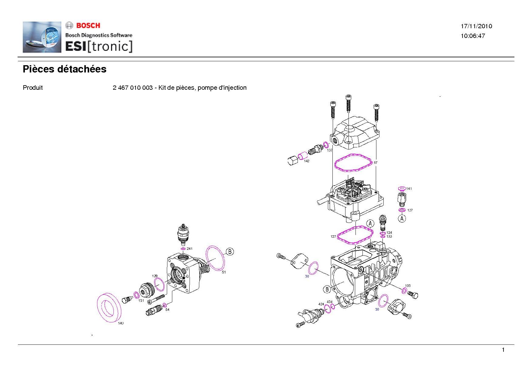
Seal kit
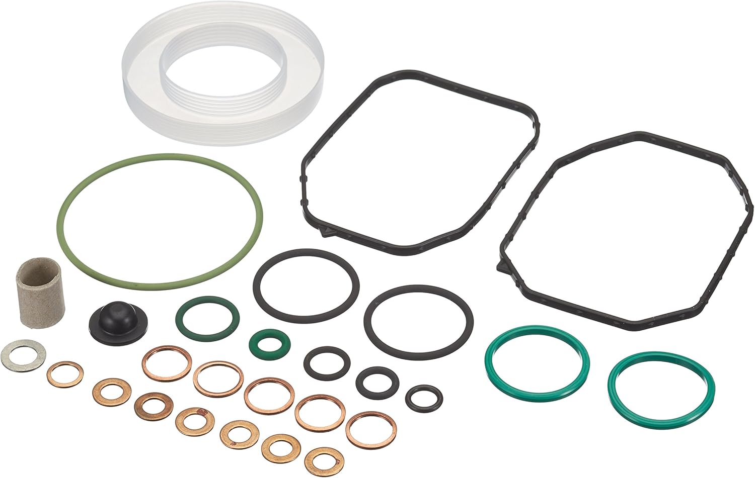
| Part Number | Brand | Link | Price | Description |
|
2467010003 |
BOSCH | Autodoc | £13. 49 (18/02/2026) |
BOSCH VP36 EDC PUMP SEAL KIT |
|
2467010003 |
BOSCH | Amazon UK | £21.66 (18/02/2026) |
BOSCH VP36 EDC PUMP SEAL KIT |
|
2467010003 |
BOSCH | ebay UK | Various (18/02/2026) |
BOSCH VP36 EDC PUMP SEAL KIT |
|
2467010003 |
BOSCH | ebay Germany | Various (18/02/2026) |
BOSCH VP36 EDC PUMP SEAL KIT |
Parts
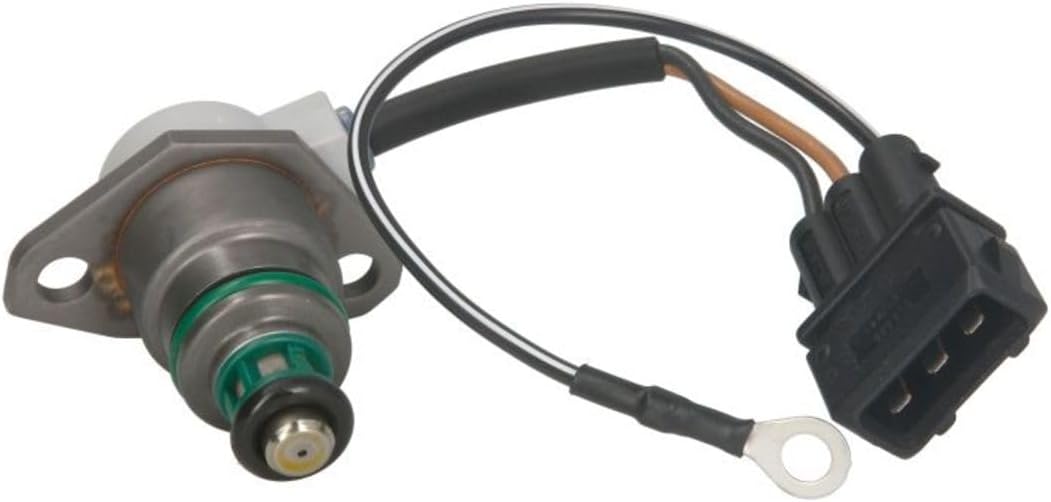
Injection quantity solenoid
| Part Number | Brand | Description |
|
0281002131 |
BOSCH | Commencement of injection valve (Advance/Retard Solenoid) |
Tools
DTI Adapter / Bosch VE Pump / M10 (The best one you can buy)
| VW Part No | 3133; VW3133 |

Press the picture to purchase
DTI Gauge + Cam TDC Tool (Needs to be small to do job on car)

Press the picture to purchase
Torque Specs
| Torque Spec | Bolt/Nut |
| 20Nm | Camshaft Caps |
| 20Nm | Injection Pump Dynamic Tensioner |
| 40Nm | Injection Pump Static Tensioner |
| 12.5Nm | Injection Pump Lock screw with shim |
| 30Nm | Injection pump lock screw |
| 20Nm | Injection Pump seal plug |
| 45Nm | Timing Gear Injection Pump |
| 160Nm | Camshaft Pulley Injection Pump side |
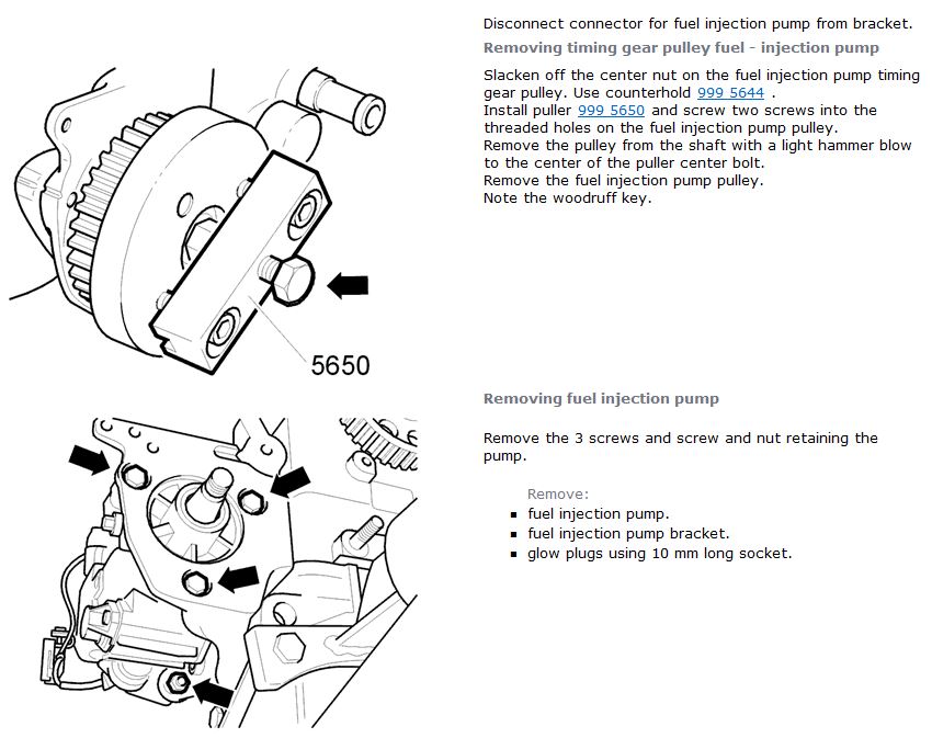
Pump Removal
INA Tension Guide
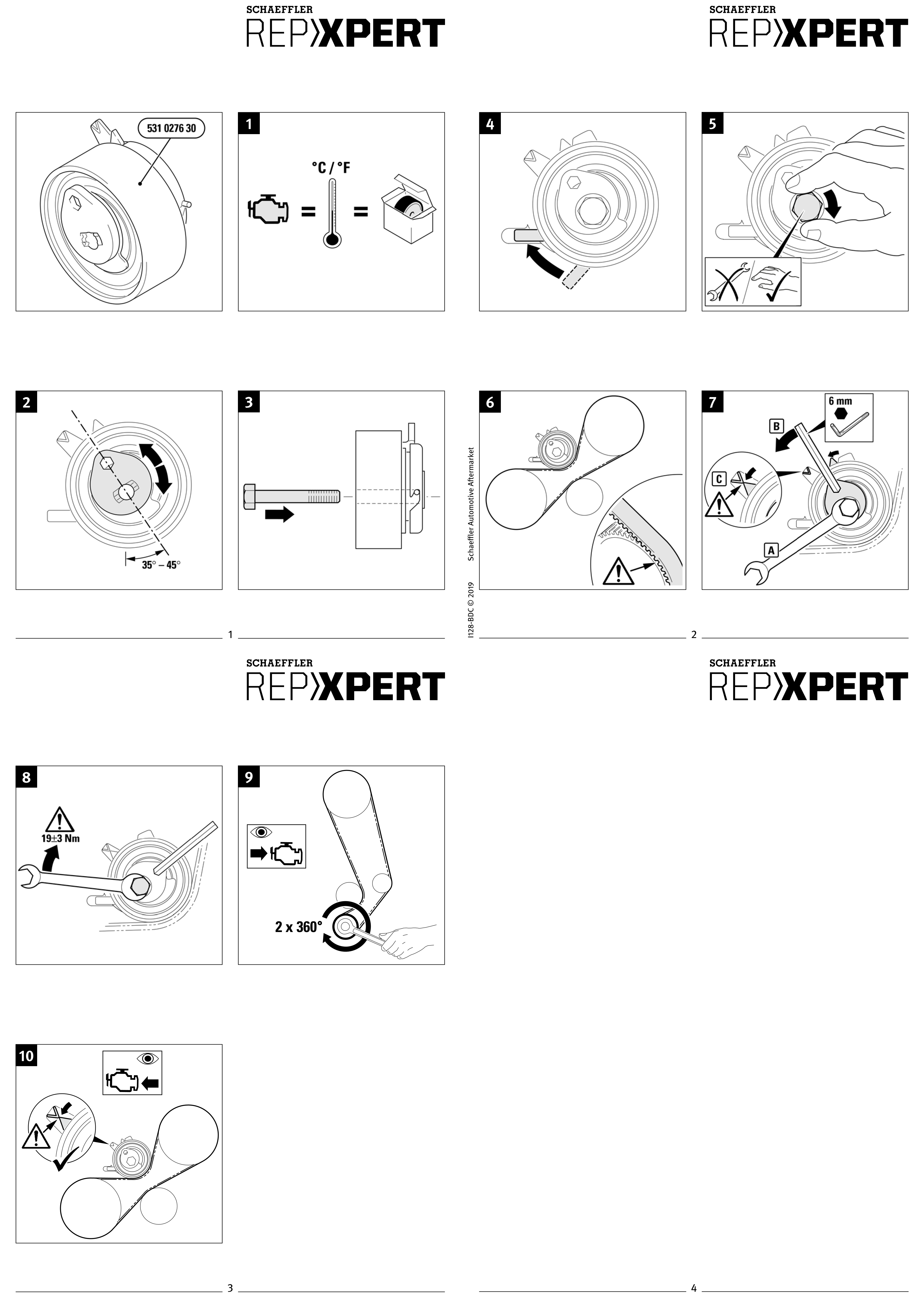
Setting initial pump timing
Please follow the steps below to set up the initial pump timing.
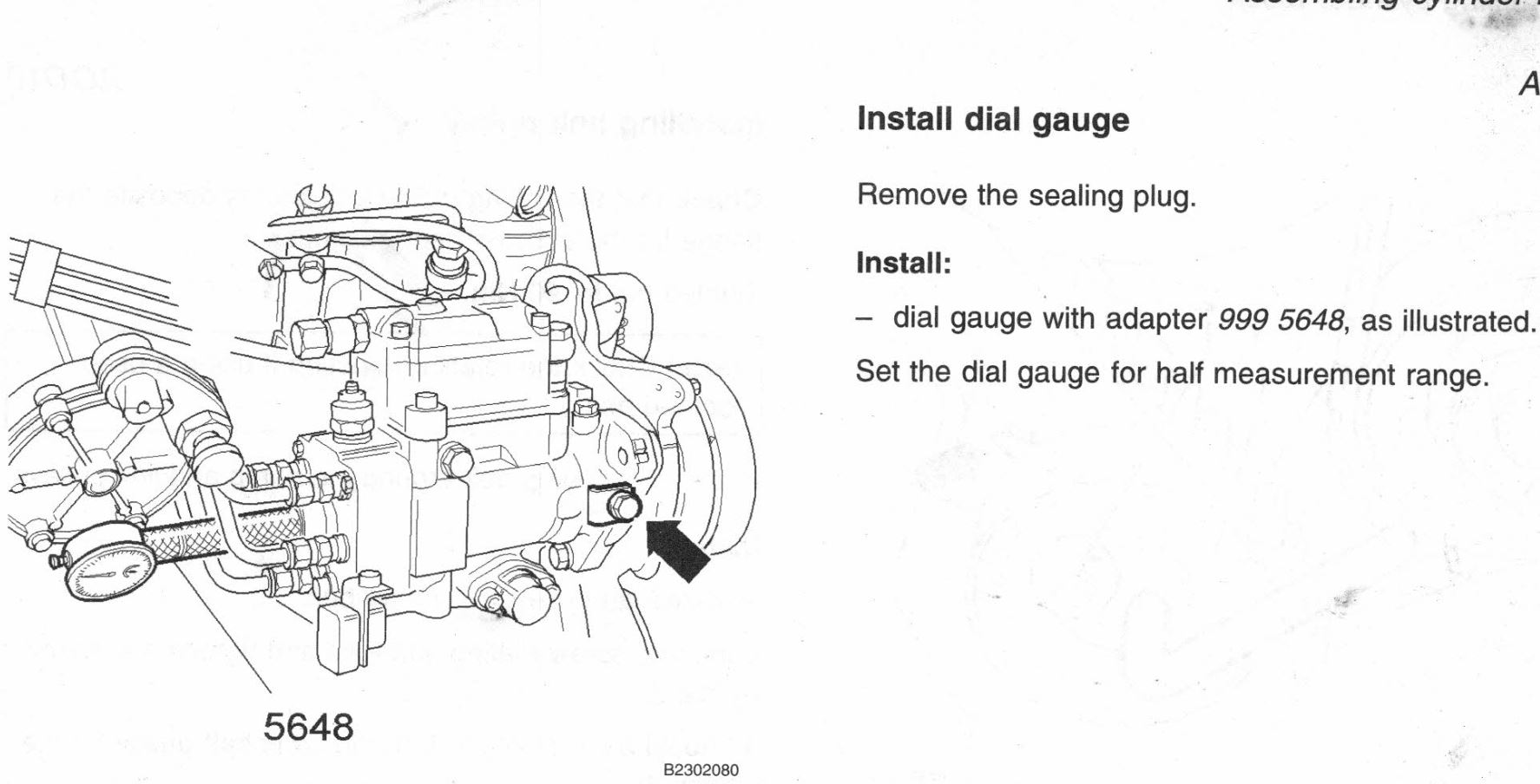
Install Dial Gauge
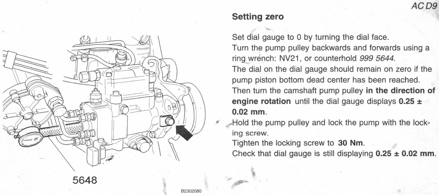
Setting Zero
Installing Static Tensioner
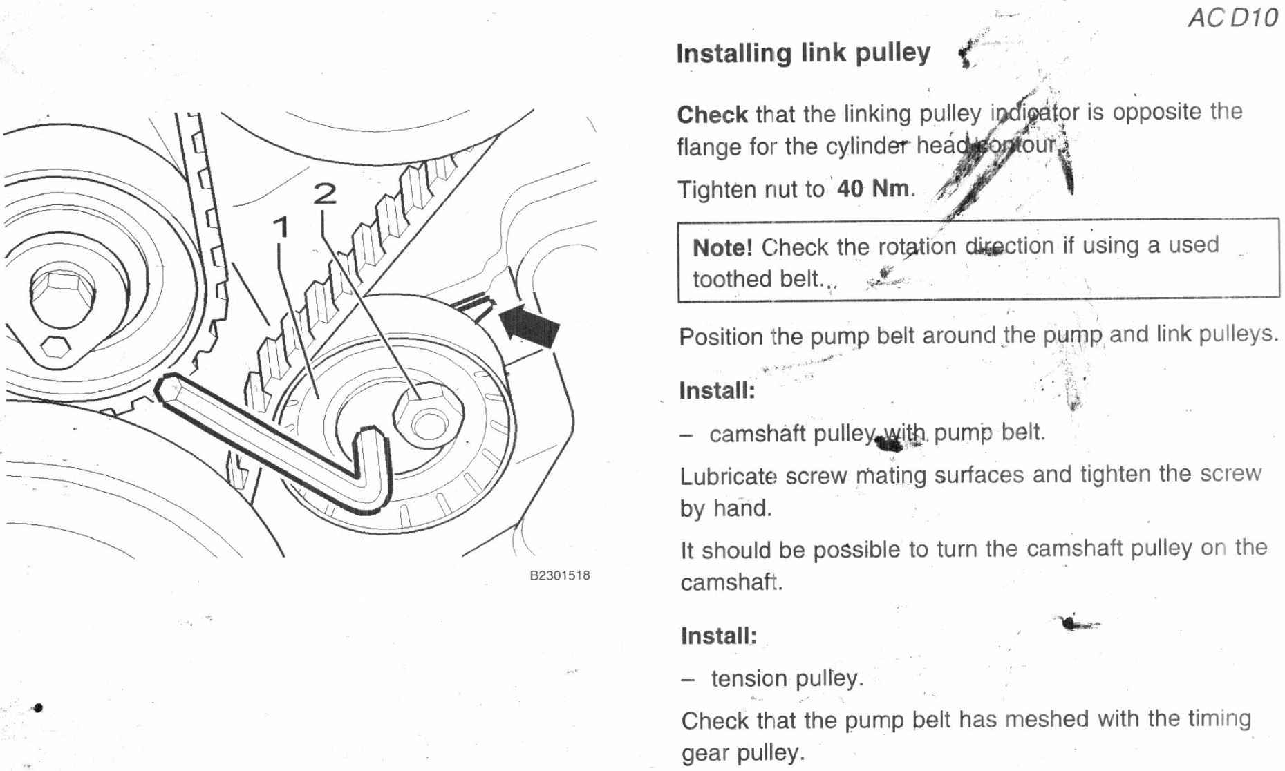
Installing Dynamic Tensioner
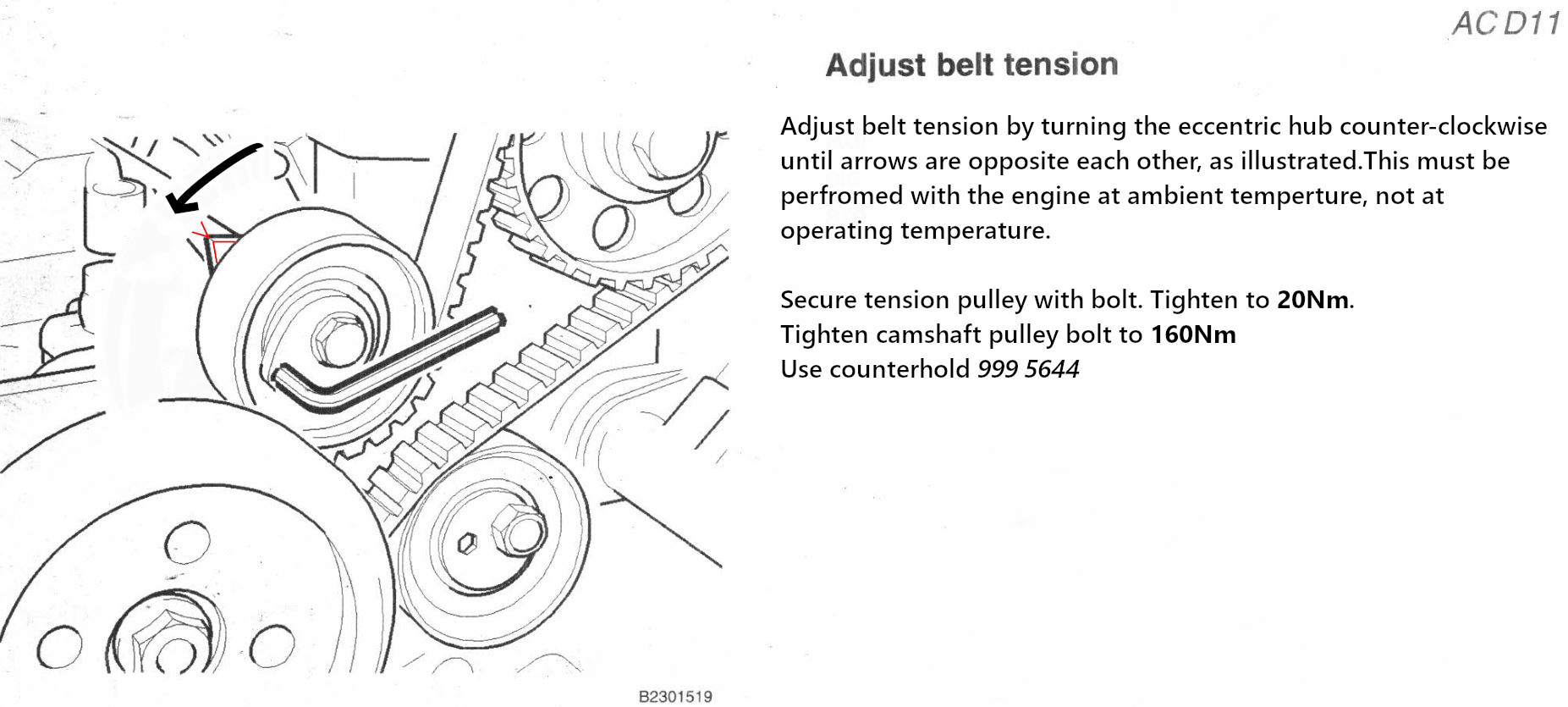
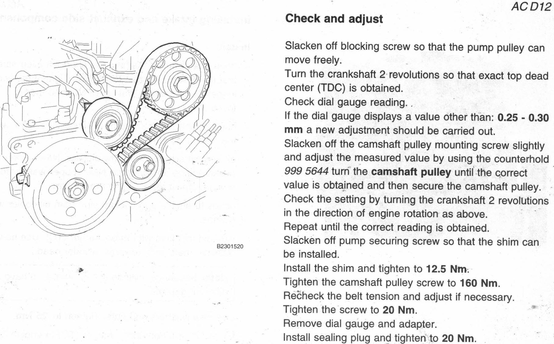
Check and Adjust
INJECTION PUMP ELECTRICAL TESTING
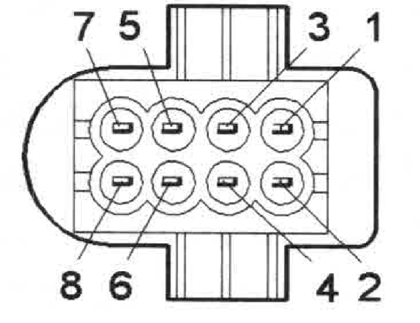
Fuel Pump Connector Terminals
Fuel Pump Temperature Sensor
Fuel Pump Connector—Fuel Pump Side
| Connector | Terminal | Checking | Unit | Set Value | Min | Max | Notes |
| 8—pin Fuel injection pump | 1 — 2 | Fuel regulator position sensor | Ω | 5 | 7 | Ignition off. — Disconnect 8-pin fuel injection pump connector. Connect an ohmmeter between fuel injection pump connector terminals 1 and 2 (fuel pump (FP) side) and then between terminals 2 and 3 (fuel injection pump side). The ohmmeter should read between 5 Ohms and 7 Ohms in both cases. | |
| 8—pin Fuel injection pump | 2 — 3 | Fuel regulator position sensor | Ω | 5 | 7 | Ignition off. — Disconnect 8-pin fuel injection pump connector. Connect an ohmmeter between fuel injection pump connector terminals 1 and 2 (fuel pump (FP) side) and then between terminals 2 and 3 (fuel injection pump side). The ohmmeter should read between 5 Ohms and 7 Ohms in both cases. | |
| 8—pin Fuel injection pump | 5 — 6 | Fuel regulator | Ω | 0.5 | 2.5 | Ignition off. — Disconnect 8-pin fuel injection pump connector. Connect an ohmmeter between fuel injection pump connector terminals 5 and 6 (fuel pump (FP) side). The ohmmeter should read between 0.5 Ohms and 2.5 Ohms in both cases. | |
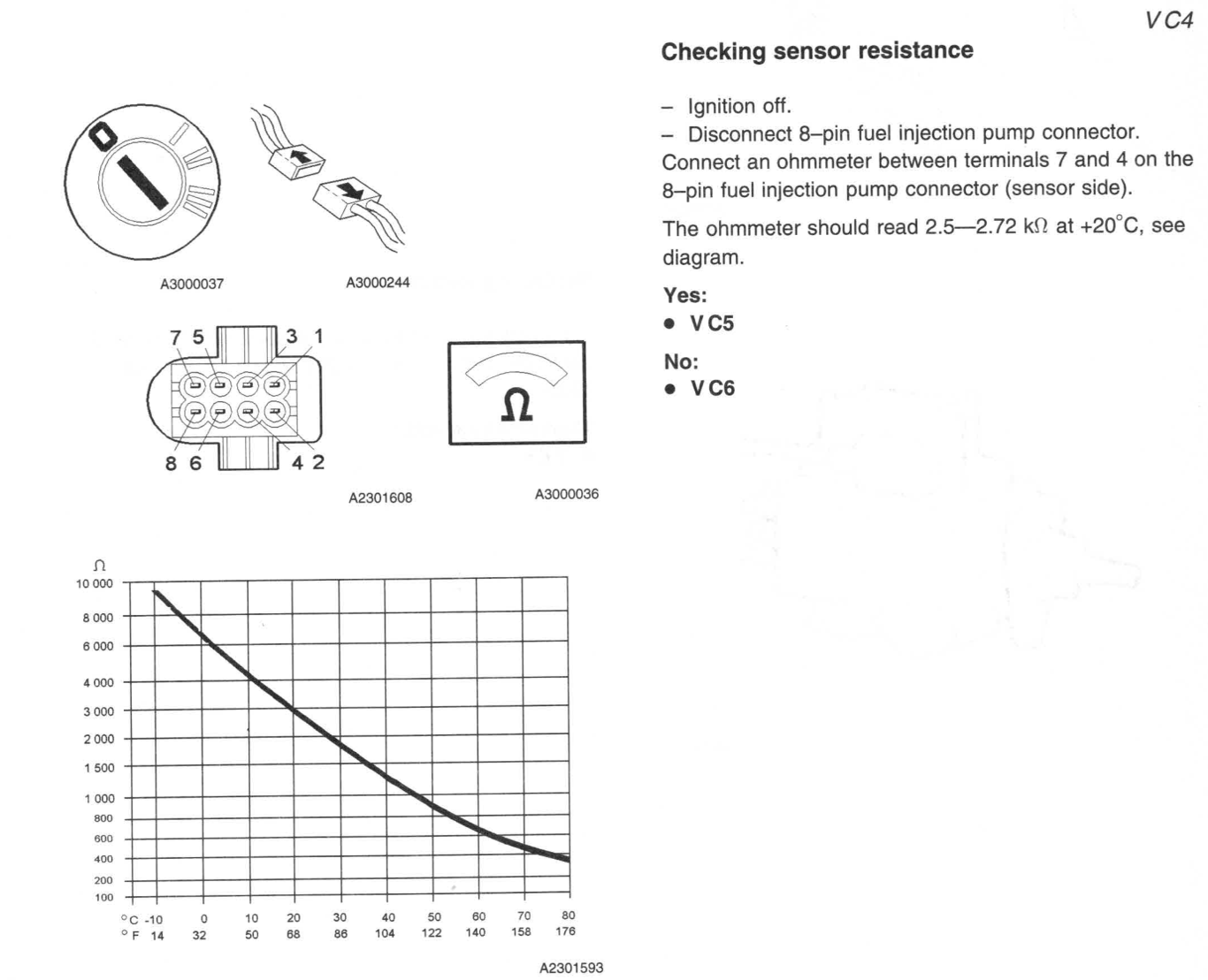
| 8—pin Fuel injection pump | 7—4 | Fuel temperature sensor | kΩ | 2.5 | 2.75 | Ignition off.— Disconnect 8-pin fuel injection pump connector. Connect an ohmmeter between terminals 7 and 4 on the 8-pin fuel injection pump connector (sensor side). The ohmmeter should read 2.5—2.72 kΩ at +20°C, see diagram. | |
| 8—pin Fuel injection pump | 1—Ground | Fuel shut off solenoid | Ω | 6.9 | 7.9 | Resistance in winding between terminals 1—ground: 6.9—7.9 Ω |
Fuel Pump Connector—ECU Side
| Connector | Terminal | Checking | Unit | Set Value | Min | Max | Ignition | Main Relay | Notes |
| 3—pin Fuel injection pump | 1—Ground | Signal Cable | V | <
2 |
2 | ON | ON | With ignition on, main relay on and the 3—pin fuel injection pump connector disconnected, the voltage between the 3-pin fuel injection pump connector terminal 1 (engine control module (ECM) side) and ground should be less than. 2 V. | |
| 3—pin Fuel injection pump | 2—Ground | Signal Cable | Ohms | >20 | 20 | OFF | OFF | With ignition off, main relay off (this may take up to 6 minutes) and 3-pin fuel injection pump connector disconnected, the resistance between the 3—pin fuel injection pump connector terminal 2 and ground should be greater than 20 Ohms, otherwise there is a short-circuit to ground in the cable. | |
| 3—pin Fuel injection pump | 3—Ground | Power Cable | V | Batt Voltage | Batt Voltage | Batt Voltage | ON | ON | Ignition on— Wait until the main relay is activated. Connect a voltmeter between 3-pin fuel injection pump connector terminal 3 and ground. The voltmeter should read battery voltage. |
| 3—pin Fuel injection pump | 3—3 Main Relay | Power Cable | Ohms | 0 | 0 | 0 | N/A | N/A | Check circuit between 3-pin fuel injection pump connector terminal 3 and main relay terminal 3 for an intermittent open-circuit |
| 8—pin Fuel injection pump | 1—Ground | Power Cable | V | >1.5—<3.5 | 1.5 | 3.5 | ON | ON | With the ignition on, the main relay activated and the 8—pin fuel injection pump connector disconnected, the voltage between the 8—pin fuel injection pump connector terminal 1 (engine control module (ECM) side) and ground should be between 1.5 and 3.5 V. |
| 8—pin Fuel injection pump | 2—Ground | Signal Cable | V | >4—<6 | 4 | 6 | ON | ON | With the ignition on, the main relay activated and the 8—pin fuel injection pump connector disconnected, the voltage between the 8-pin fuel injection pump connector terminal 2 (engine control module (ECM) side) and ground should be between 4.0 and 6.0 V. |
| 8—pin Fuel injection pump | 3—Ground | Power Cable | V | >0.5—<4.5 | 0.5 | 4.5 | ON | ON | With the ignition on, the main relay activated and the 8—pin fuel injection pump connector disconnected, the voltage between the 8—pin fuel injection pump connector terminal 3 (engine control module (ECM) side) and ground should be between 0.5 and 4.5 V. |
| 8—pin Fuel injection pump | 4—Ground | Ground Lead | Ohms | 0 | 0 | 0 | OFF | OFF | With the ignition off, main relay off and the fuel temperature sensor connector disconnected, the resistance between the fuel temperature sensor connector terminal 4 (engine control module (ECM) side) and ground should be approx. 0 Ohms. |
| 8—pin Fuel injection pump | 5—Ground | Power Cable | V | Batt Voltage | Batt Voltage | Batt Voltage | ON | ON | Ignition on and main relay on. Disconnect 8—-pin fuel injection pump connector. Connect a voltmeter between fuel injection pump connector terminal 5 and ground. The voltmeter should read battery voltage. |
| 8—pin Fuel injection pump | 6—Ground | Signal Cable | V | >1 | >1 | ON | ON | With the ignition on and the 8-pin fuel injection pump connector disconnected the voltage between the 8—pin fuel injection pump connector terminal 6 (engine control module (ECM) side) and ground should be greater than 1 V. Otherwise there is an open-circuit or short-circuit to ground in the cable. | |
| 8—pin Fuel injection pump | 7—Ground | Signal Cable | V | 5 | ON | ON | With the ignition on and the 8-pin fuel injection pump connector disconnected, the voltage between the 8—pin fuel injection pump connector terminal 7 (engine control module (ECM) side) and ground should be approx. 5 V. |
ECU Terminals
| Terminal | Signal Type | Ignition on | Engine idling | Miscellaneous | Scrolling value VST |
| #A1 | Power supply, fuel regulator position sensor (Sensor in injection pump) |
U=2.5 V UAC=0.4—0.5 V |
U=2.5 V UAC=0.6 V |
U increases with quantity of fuel injected | |
| #A2 | Signal ground, boost pressure sensor | Ulow | Ulow | ||
| #A3 | Signal, intake air temperature (IAT) sensor (Sensor in mass air flow(MAF) sensor) (Measuered relative to #A18) |
+10C: U=4.1V +30C: U=3.3V +50C: U=2.5V +80C: U=2.5V +100C: U=1.0V |
U decreases with increasing intake air temperature (IAT) | ||
| #A4 | Signal , needle lift sensor (Measured relative to #A18) |
U=0.2V | U increases with air mass | ||
| #A5 | |||||
| #A6 | |||||
| #A7 | |||||
| #A8 | |||||
| #A9 | |||||
| #A10 | |||||
| #A11 | |||||
| #A12 | |||||
| #A13 | |||||
| #A14 | |||||
| #A15 | |||||
| #A16 | |||||
| #A17 | |||||
| #A18 | |||||
| #A19 | |||||
| #A20 | |||||
| #A21 | |||||
| #A22 | |||||
| #A23 | |||||
| #A24 | |||||
| #A25 | |||||
| #A26 | |||||
| #A27 | |||||
| #A28 | |||||
| #A29 | |||||
| #A30 | |||||
| #A31 | |||||
| #A32 | |||||
| #A33 | |||||
| #A34 | |||||
| #A35 | |||||
| #A36 | |||||
| #A37 | |||||
| #A38 | |||||
| #A39 | |||||
| #A40 | |||||
| #A41 | |||||
| #A42 | |||||
| #A43 | |||||
| #B1 | |||||
| #B2 | |||||
| #B3 | |||||
| #B4 | |||||
| #B5 | |||||
| #B6 | |||||
| #B7 | |||||
| #B8 | |||||
| #B9 | |||||
| #B10 | |||||
| #B11 | |||||
| #B12 | |||||
| #B13 | |||||
| #B14 | |||||
| #B15 | |||||
| #B16 | |||||
| #B17 | |||||
| #B18 | |||||
| #B19 | |||||
| #B20 | |||||
| #B21 | |||||
| #B22 | |||||
| #B23 | |||||
| #B24 | |||||
| #B25 | |||||
| #B26 | |||||
| #B27 | |||||
| #B28 | |||||
| #B29 | |||||
| #B30 | |||||
| #B31 | |||||
| #B32 | |||||
| #B33 | |||||
| #B34 | |||||
| #B35 | |||||
| #B36 | |||||
| #B37 | |||||
| #B38 | |||||
| #B39 | |||||
| #B40 | |||||
| #B41 | |||||
| #B42 | |||||
| #B43 | |||||
TIMING BELT
How to remove cam belt
1. Set the flywheel to TDC using the mark at the bottom of the gearbox, the pointer should point to a “V” notch on the flywheel.
2. Remove the auxiliary belt and tensioner.

3. Install the Volvo locking tool on the vibration damper if the car is a TDC the tool with fit.

4. Lock the injection pump, remove the keeper and tighten bolt.

5. Using tool to hold the camshaft pulley on the injection pump side and loosen the camshaft bolt

6. Remove injection pump tensioner and remove injection pump belt.
7. Remove camshaft pulley on injection pump side
8. Injection pump side is done for now move over to cam belt side
9. Using a ¾ Breaker bar a ¾ 16" extension and an axle stand lossen the crankshaft bolt

10. Using a 6mm Hex loosen the 4 small bolts around the crank bolt.
11. Remove the vibration damper tool.
12. Remove the crank bolt and four small bolts
13. Remove the vibration damper, if it does not come off right away use soft hammer and hit round the edges to break free.
14. Remove metal cover over timing belt.
15. Remove timing belt tensioner and belt.
16. Place tool in end of camshaft injection pump side, you may need to use the camshaft pulley to move the cam but should only be a little,
the more the slot does not match the more the timing was out.

17. With this tool installed hold the camshaft using counterhold tool and lossen the camshaft bolt on the crank side.
18. Leave the cam pulley lose
19. At this point
- Cam shaft is at TDC
- Both timing belts are removed
- Check flywheel mark for crank TDC
- Get ready to install new timing belt.
How to install new timing belt
1. Check Flywheel is at TDC using mark
2. Check Camshaft is at TDC using tool
3. Finger tight the cam pully on the crank side
4. Install timing belt tensioner and fit belt
5. Tension belt using INA tension guide
6. Counterhold campulley and tourque to spec
7. Rotate engine twice using tool in cam pulley
8. Check Timing belt tensioner mark is still in position

9. Check flywheel is at TDC
10. Check Camshaft is at TDC using tool in slot.
11. If camshaft, flyweel and tensioner marks are good continue if not go back and redo.
12. Fit metal cover
13. Fit vibration damper and install new crank bolt with diamond washer and four small bolts hand tighten.
14. Install vibration damper locking tool
15. Torque four small bolts
16. Tourque crank bolt to 160Nm + 180 Degrees, use axle stand and big breaker bar for the angle torque
(Mark bolt with marker or use angle gauge to know how much angle you have put on bolt)
17. Remove vibration damper tool.
18. Install auxiliary belt tensioner and belt.
19. Crank shaft side done move over to injection pump side.
INA TENSION GUIDE

AUXILIARY BELT
Exploded diagram

Belt Routing with A.C
OIL CHANGE
Oil Specfications
| Engine | Service interval (km)/(mil) | Volume (litres) | Grade | Viscosity | Part number |
| D5252T | (15,000 / 20,000) (9,300 / 12,400) | Approx. 6.0 | ACEA A3/B3/B4 | SAE 5W-40 | 1161630, -631, -639 |
Oil Change Instructions

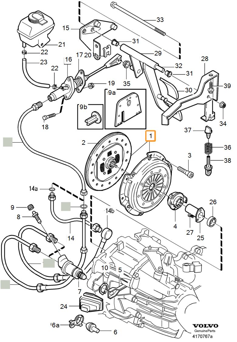
V70/S70 MSA 15.7 M56 CLUTCH
V70/S70 VOLVO PARTS DIAGRAM

V70/S70 VOLVO DIAGRAM & PART NUMBERS
| Fig | Description | Qty. | Part Number | INFO |
| 1 | Clutch kit | 1 | 274156 | |
| 2 | Driven plate | 1 | 9480896 | |
| 3 | Hex. socket screw | 6 | 959219 | |
| 4 | Control cylinder | 1 | 9181322 | REPL 1 PCS 9463525. |
| Control cylinder | 1 | 9463525 | REPL 1 PCS 6900012. | |
| Control cylinder | 1 | 6900012 | REPL 1 PCS 8667661 | |
| Control cylinder | 1 | 8667661 | ||
| 5 | Quick coupling | 1 | 9181729 | FOR 9463525, 9181322. |
| 6 | Rubber seal | 1 | 9181326 | |
| 7 | Flange screw | 2 | 982759 | |
| 8 | Sealing ring | 1 | 1381798 | O.DIA 41 mm |
| Sealing ring | 1 | 8675580 | O.DIA 44 mm, (9183971) | |
| 9 | Clutch pipe | 1 | 9480293 | (9176473) |
| 9a | O-ring | 1 | 9143918 | |
| 10 | Clutch line | 1 | 9480294 | (9181337) Also order clutch pipe 9480293. |
| 12 | Adapter | 1 | 9181332 | |
| 13 | Lock brace | 3 | 9181827 | |
| 14 | Rubber cap | 1 | 656456 | |
| 15 | Clutch line | 1 | 9143757 | -1998 |
| Clutch line | 1 | 9183753 | 1999- | |
| 16 | Master cylinder | 1 | 9181340 | -1998 |
| Master cylinder | 1 | 9181766 | 1999- | |
| 16a | Lock brace | 1 | 9181827 | 1999- |
| 16b | Sealing | 1 | 9207806 | 1999- |
| 16c | Washer | 1 | 9183728 | 1999- |
| 16d | Position sensor | 1 | 9472979 | 1999- |
| 17 | Flange nut | 2 | 985921 | |
| 18 | Lock brace | 1 | 983479 | (30636040)(969159) |
| 19 | Decanter | 1 | Master cylinder servo cylinder -1998 5CYL L.H.D | |
| Decanter | 1 | Master cylinder servo cylinder -1998 5CYL R.H.D | ||
| Decanter | 1 | Master cylinder servo cylinder -1998 DSL L.H.D | ||
| Decanter | 1 | Master cylinder servo cylinder -1998 DSL R.H.D | ||
| 20 | Rubber hose | x | 9157190 | LG 410 mm |
| 21 | Hose clamp | 2 | 976568 | |
| 22 | Pedal arrangement | 1 | Brake pedal with assembly parts MAN.TRANS R.H.D | |
| 23 | Flange screw | 1 | 985186 | |
| 24 | Washer | 1 | 986501 |
Service instructions:
At Volvo, there are special tools for installing the clutch that should be used. This will prevent the vibrating of the clutch. (1011436, 1011437).
When installing the clutch without these tools you risk the possibility of the clutch shuddering. A complaint will not be accepted if the tools are not used.
Use the slave cylinder 8667661 (1006083) from years model 98. The standard Release bearing only fits up to 97!
Parts List
V70/S70 Clutch Kit
| Part Description | Brand | Part Number(s) | Price | LINK |
| Clutch Kit + Slave Cylinder | LuK | 624 2231 33 | £ 194,32 (22/01/25) |
LINK |
| Clutch Kit | SACHS | 3000 841 501 | £ 154,04 (22/01/25) |
LINK |
| Screw/ Bolt Inner Hexagon M8 20mm Flywheel Pressure plate |
SKANDIX | 986320 | € 0,58 (22/01/25) |
LINK |
V70/S70 Slave Cylinder
| Part Description | Brand | Part Number(s) | Price | LINK |
| Central Slave Cylinder | SACHS | 3182 654 199 | £ 89,72 (22/01/25) |
LINK |
| Central Slave Cylinder | LuK | 510 0010 10 | £ 87,37 (22/01/25) |
LINK |
| Central Slave Cylinder | AISIN | CSCM-901 | £ 78,70 (22/01/25) |
LINK |
850 Clutch Release Bearing
| Part Description | Brand | Part Number(s) | Price | LINK |
| Clutch release bearing | SACHS | 3151 269 332 | £ 34,70 (22/01/25) |
LINK |
Volvo Special Tools
| Tool | Brand | Part Number(s) | Price | Link |
| Press tool, Clutch | Volvo | 9995662 | €147,58 (22/01/25) |
LINK |
| Centering tool, Clutch plate | Volvo | 9995663 | €86,09 (22/01/25) |
LINK |
850 CLUTCH
850 D5252T CLUTCH PARTS DIAGRAM
850 D5252T CLUTCH PART NUMBERS
| Fig | Description | Qty. | Part Number | INFO |
| 1 | Clutch kit | 1 | 274156 | (272229) |
| 2 | Driven plate | 1 | 9480896 | (9176188) |
| 3 | Hex. socket screw | 6 | 959219 | M8x16 |
| 4 | Release bearing | 1 | 9181651 | (9163506)(9143472) |
| 5 | Release fork | 1 | 9143486 | (3502595)(9143165) |
| 6 | Pivot pin | 1 | 3502145 | -1995, REPL 1PCS 9163598-7,, 1PCS 9143962-0. |
| Pivot pin | 1 | 9163598 | ||
| 6a | Ball seat | 1 | 9143962 | |
| 7 | Control cylinder | 1 | 9181017 | EXC B5234T4, (6843128) |
| 8 | Bleeder nipple | 1 | 1221940 | |
| 9 | Rubber cap | 1 | 656456 | |
| 9a | Heat insulation | 1 | 9181829 | (FI), (NO), (SE) |
| 9b | Clip | 1 | 9181832 | (FI), (NO), (SE) |
| 10 | Snap ring | 1 | 914463 | |
| 14 | Clutch pipe | 1 | 9176473 | |
| 14a | O-ring | 1 | 9143918 | |
| 14b | Clutch line | 1 | 9181397 | |
| 15 | Bracket | 1 | Brake pedal with assembly parts MAN.TRANS R.H.D -1996 | |
| 16 | Master cylinder | 1 | 9163882 | (3502567) |
| 17 | Sealing | 1 | 3502854 | |
| 18 | Press screw | 2 | 965503 | |
| 19 | Flange nut | 2 | 985921 | |
| 20 | Lock brace | 1 | 989037 | -1996 |
| Lock brace | 1 | 969159 | 1997 | |
| 21 | Decanter | 1 | ||
| Decanter | 1 | |||
| Decanter | 1 | |||
| 22 | Hose clamp | 2 | 1389647 | -1995 |
| Hose clamp | 2 | 976568 | 1996- | |
| 23 | Hose | 1 | 944574 | -1995, LG 240 mm |
| Rubber hose | x OP | 9157190 | 1996-, LG 240 mm | |
| 24 | Bellows | 1 | 6843840 | 4DRS CH -APP 79123, 5DRS CH -APP 3766,, (3520132) |
| Bellows | 1 | 6843840 | 4DRS CH APP 79124-., 5DRS CH APP 3767-. | |
| 25 | Sleeve | 1 | 1381799 | Manual transmission M56 -1994 |
| Sleeve | 1 | 1381799 | Manual transmission M56 1995 | |
| Sleeve | 1 | 1381799 | Manual transmission M56 1996- | |
| Sleeve | 1 | 1381799 | Manual transmission M59 | |
| Sleeve | 1 | 1381799 | Manual transmission M58 | |
| 26 | Sealing ring O.DIA 41 mm |
1 | 1381798 | Manual transmission M56 -1994 |
| Sealing ring O.DIA 44 mm, (9183971) |
1 | 8675580 | Manual transmission M56 -1994 | |
| Sealing ring O.DIA 41 mm |
1 | 1381798 | Manual transmission M56 1995 | |
| Sealing ring O.DIA 44 mm, (9183971) |
1 | 8675580 | Manual transmission M56 1995 | |
| Sealing ring O.DIA 41 mm |
1 | 1381798 | Manual transmission M56 1996- | |
| Sealing ring O.DIA 44 mm, (9183971) |
1 | 8675580 | Manual transmission M56 1996- | |
| Sealing ring O.DIA 41 mm |
1 | 1381798 | Manual transmission M59 | |
| Sealing ring O.DIA 44 mm, (9183971) |
1 | 8675580 | Manual transmission M59 | |
| Sealing ring O.DIA 41 mm |
1 | 1381798 | Manual transmission M58 | |
| Sealing ring O.DIA 44 mm, (9183971) |
1 | 8675580 | Manual transmission M58 | |
| 27 | Screw | 3 | 3502870 | Manual transmission M56 -1994 |
| Screw | 3 | 3502870 | Manual transmission M56 1995 | |
| Screw | 3 | 3502870 | Manual transmission M56 1996- | |
| Screw | 3 | 3502870 | Manual transmission M59 | |
| Screw | 3 | 3502870 | Manual transmission M58 | |
| 28 | Bracket | 1 | Brake pedal with assembly parts MAN.TRANS R.H.D -1996 | |
| 29 | Clutch pedal | 1 | 3546106 | REPL 1PCS 9173744-5, 1PCS 969159-3. |
| Clutch pedal | 1 | 9173744 | 1997- | |
| 30 | Pedal pad | 1 | 3546020 | |
| 31 | Bushing | 2 | 3516125 | |
| 32 | Shaft | 1 | 3546111 | |
| 33 | Flange screw | 1 | 985334 | |
| 34 | Flange lock nut | 1 | 985868 | |
| 35 | Bushing | 1 | 3546427 | |
| 36 | Helper spring | 1 | 3546410 | |
| 37 | Spring seat | 1 | 9140019 | |
| 38 | Spring seat | 1 | 3546113 | |
| 39 | Flange screw | 1 | 985186 | |
| Washer | 1 | 986501 |
Service instructions:
At Volvo, there are special tools for installing the clutch that should be used. This will prevent the vibrating of the clutch. (1011436, 1011437).
When installing the clutch without these tools you risk the possibility of the clutch shuddering. A complaint will not be accepted if the tools are not used.
Use the slave cylinder 8667661 (1006083) from years model 98. The standard Release bearing only fits up to 97!
Parts List
850 D5252T Clutch Kit
| Part Description | Brand | Part Number(s) | Price | LINK |
| Clutch Kit + Slave Cylinder | LuK | 624 2231 33 | £ 194,32 (22/01/25) |
LINK |
| Clutch Kit | SACHS | 3000 841 501 | £ 154,04 (22/01/25) |
LINK |
| Screw/ Bolt Inner Hexagon M8 20mm Flywheel Pressure plate |
SKANDIX | 959219 | € 1,92 (25/01/25) |
LINK |
850 D5252T Slave Cylinder
| Part Description | Brand | Part Number(s) | Price | LINK |
| Clutch Slave Cylinder | SACHS | 6283 600 495 | £ 76,59 (25/01/25) |
LINK |
| Clutch Slave Cylinder | TRW | PJH108 | £ 60,83 (25/01/25) |
LINK |
850 D5252T Ball Socket Clutch fork
| Part Description | Brand | Part Number(s) | Price | LINK |
| Ball Socket Clutch fork | SKANDIX | 9143962 | € 18,13 (22/01/25) |
LINK |
850 D5252T Pivot pin, Clutch fork
| Part Description | Brand | Part Number(s) | Price | LINK |
| Ball Socket Clutch fork | SKANDIX | 9163598 | € 12,50 (22/01/25) |
LINK |
850 D5252T Clutch Release Bearing
| Part Description | Brand | Part Number(s) | Price | LINK |
| Clutch release bearing | SACHS | 3151 269 332 | £ 34,70 (22/01/25) |
LINK |
850 D5252T Release fork, Clutch
| Part Description | Brand | Part Number(s) | Price | LINK |
| Clutch release bearing | SANDIX | 9143486 | € 177,60 (22/01/25) |
LINK |
Volvo Special Tools
| Tool | Brand | Part Number(s) | Price | Link |
| Press tool, Clutch | Volvo | 9995662 | €147,58 (22/01/25) |
LINK |
| Centering tool, Clutch plate | Volvo | 9995663 | €86,09 (22/01/25) |
LINK |
PCV VALVE
If someone will ever need to change crankcase breather, don't buy it from skandix, because they're selling crap that not fit and the code is scratched off... Now they're made a tag in installation instructions" The connection is now on the other side, so the hose routing must be changed." But it doesn't make a sense to pay 5x more than it cost especially when it's still not fit.
So if you have a problem with PCV valve, better search it with a part number 038129101A ( like topran 113279)
Edvinas
PCV VALVE
| Part Description | Brand | Part Number(s) | Price | AUTODOC LINK |
eBay LINK |
|
VAICO V10-3087 Valve, engine block breather |
VAICO |
V10-3087 | £ 10,99 (27/06/2025) |
LINK | LINK |
|
TOPRAN 113 279 Valve, engine block breather |
TOPRAN |
113 279 | £ 10,77 (27/06/2025) |
LINK | LINK |
|
ORIGINAL IMPERIUM 4818 Oil Trap, crankcase breather |
IMPERIUM |
4818 | £ 12,65 (27/06/2025) |
LINK | LINK |
|
AUTOMEGA 130052810 Valve, engine block breather |
AUTOMEGA |
130052810 | £ 10,22 (27/06/2025) |
LINK | LINK |
|
PREXAparts P129028 Valve, engine block breather |
PREXAparts |
P129028 |
£ 11,48 (27/06/2025) |
||
|
VIKA 11291796601 Valve, engine block breather |
VIKA |
11291796601 |
£ 13,15 (27/06/2025) |
||
|
METZGER 2385132 Valve, engine block breather |
METZGER |
2385132 |
£ 13,23 (27/06/2025) |
||
|
Metalcaucho 35108 Valve, engine block breather |
Metalcaucho |
35108 |
£ 16,59 (27/06/2025) |
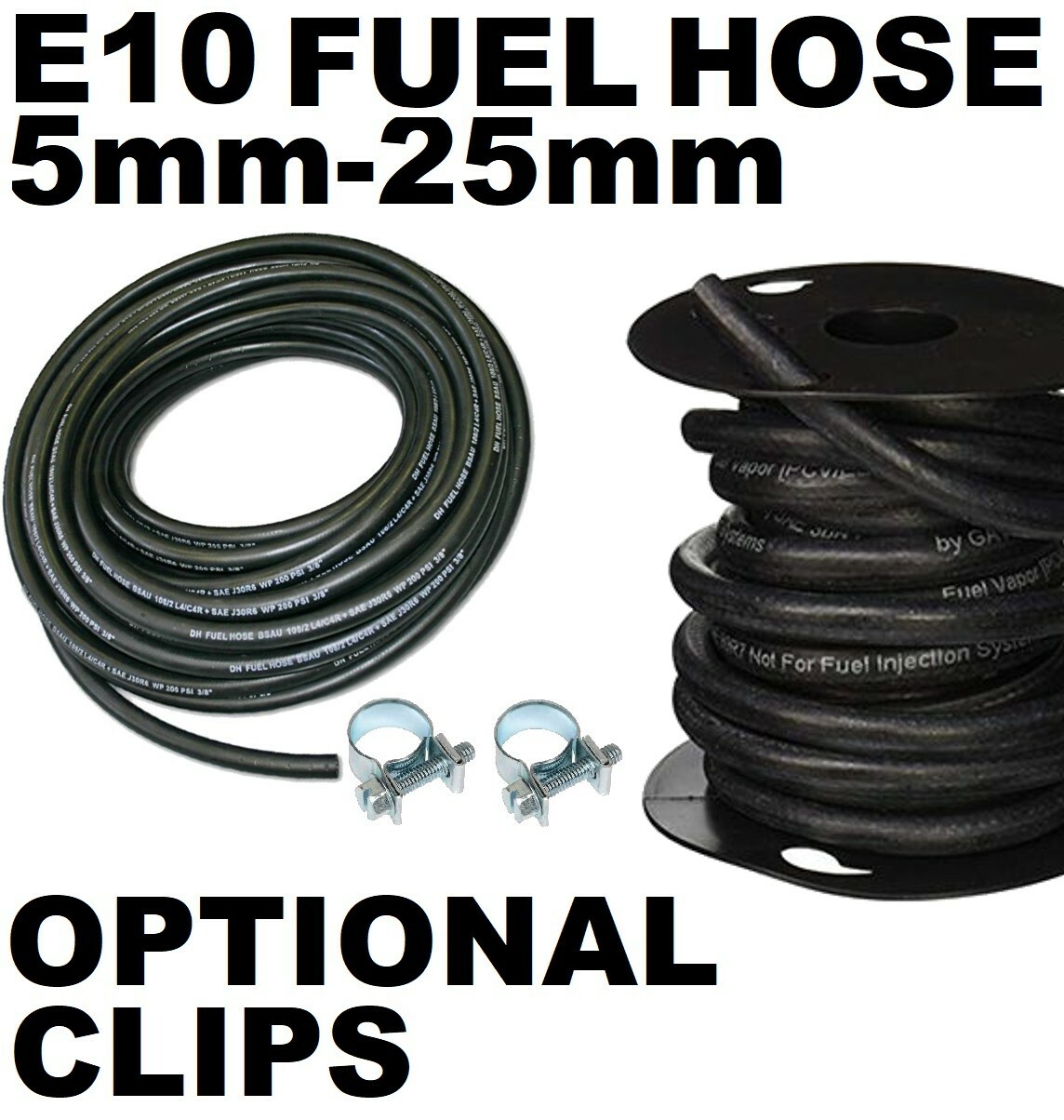
FUEL LINES
Fuel hose
I have listed a few different suppliers below to chose from, you will need 2x 6 meter lengths of hose.
| ID | Length | Quantity | eBay Link |
| 6mm | 6 Meters | 2 | LINK |
| 6mm | 6 Meters | 2 | LINK |
| 6mm | 6 Meters | 2 | LINK |
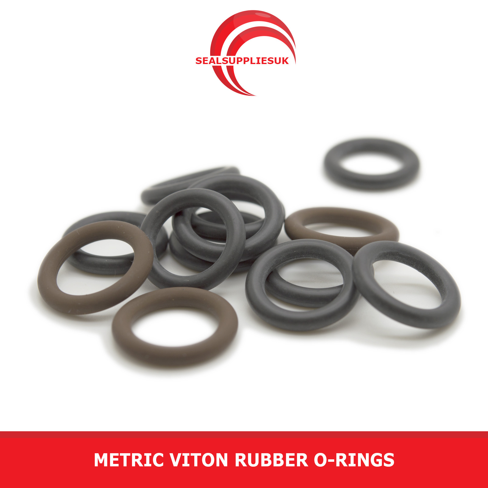
O-Rings for fuel hanger 90 Degree connector
You can replace the old rubber o-rings in the 90 degree fuel hanger connector's, the link below to the best ones I could find on eBay.
| ID | OD | Cross-Section | Quantity | Material | eBay Link |
| 8.00mm | 13.00mm | 2.50mm | 4 | Viton Rubber FKM | LINK |
Hose Clamps
| Brand | Size | Hose Size | eBay Link |
| Oetiker | 10.8-13.3mm | 6mm | LINK |
| Oetiker | 12.8-15.3mm | 8mm | LINK |

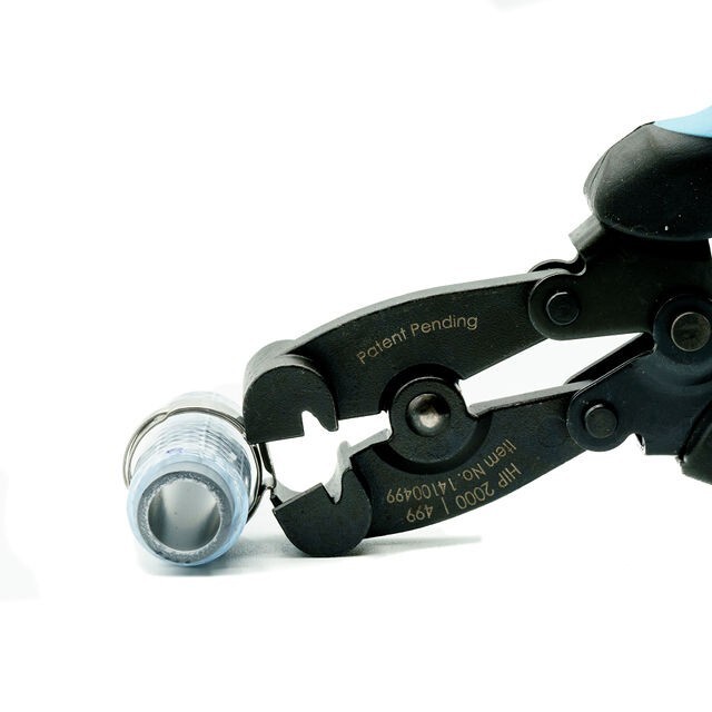
Hose Clamp Tool
| Brand | Price | eBay Link |
| Speedclean | Low | LINK |
| Oetiker 1098 | Medium | LINK |
| Oetiker HIP 2000 | 499 | High | LINK |
Starter Motor
VIDA Information
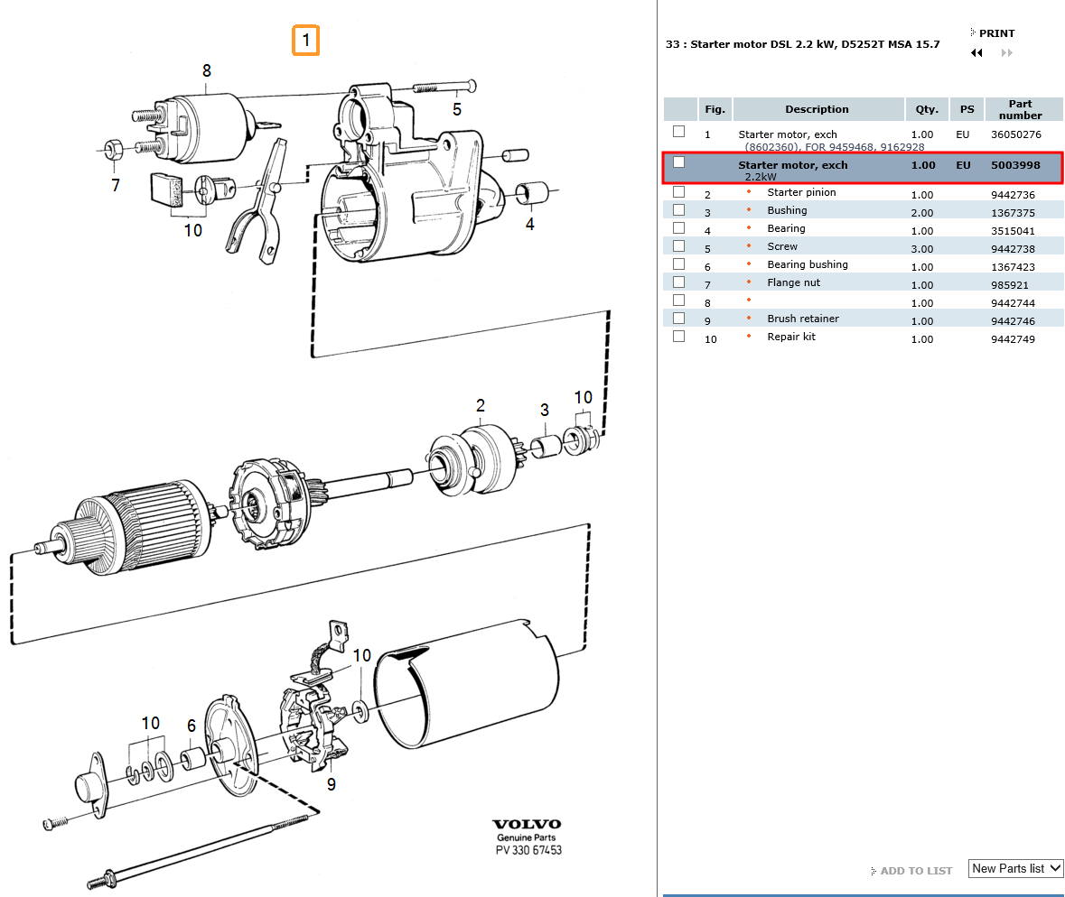
Parts
| Part Description | Brand | Part Number(s) | Price | Link |
| Starter Motor | Volvo | 5003998 | N/A | This part is discontinued. |
| Starter Motor | Volvo | 9162928 | N/A | This part is discontinued. |
| Starter Motor | RIDEX REMAN | 2S1131R |
£81.49 (15/01/2026) |
LINK |
| Starter Motor | LUCAS | LRS01357 | £170.49 (15/01/2026) |
LINK |
| Starter Motor | WALKER | WST00702 | £238.00 (15/01/2026) |
LINK |
| Starter Motor | ROTOVIS | 8017480 | £73.49 (15/01/2026) |
LINK |
Bosch 0 001 218 173 Starter motor
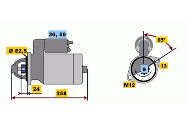
| Specification | Details |
| Manufacturer | BOSCH |
| Item Number | 0 001 218 173 |
| EAN Number | 3165142257600 |
| Condition | New |
| Price | £478.50 |
| Rated Power | 2.2 kW |
| Voltage | 12 V |
| Starter Type | Self-supporting |
| Rotation Direction | Clockwise rotation |
| Number of Teeth | 9 |
| Pinion Rest Position | 21 mm |
| Flange Diameter | 82.5 mm |
| Length | 257.5 mm |
| Clamp | 50, 30 |
BOSCH 0 986 017 480 Starter motor
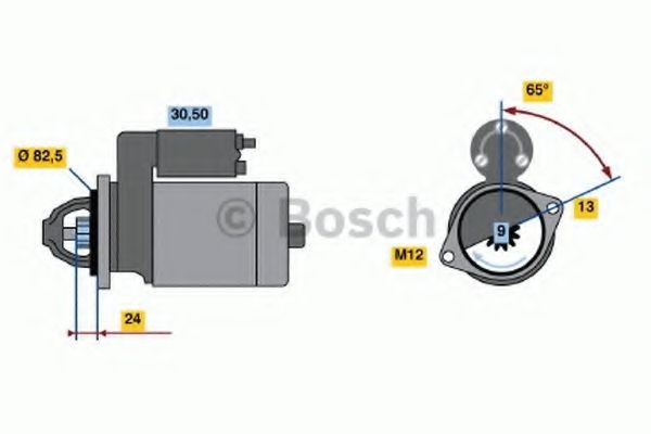
| Property | Details |
| Manufacturer | BOSCH |
| Item Number | 0 986 017 480 |
| EAN Number | 3165141163674 |
| Condition | Remanufactured (Exchange Part) |
| Price | £160.99 |
| Rated Power | 2.2 kW |
| Voltage | 12 V |
| Number of Teeth | 9 |
| Rotation Direction | Clockwise rotation |
| Starter Type | Self-supporting |
| Flange Diameter | 83 mm |
| Length | 258 mm |
| Pinion Rest Position | 21 mm |
| Clamp | 50, 30 |
| Position / Degree | Rechts (Right) |
| Number of Mounting Bores | 1 |
| Bore Diameter | 13 mm |
| Number of Threaded Holes | 1 |
| Thread Size | M12x1.75 |
| Mounting Angle | 65° |
| Jaw Opening Angle | 65° |
| Mounting Bore Angle | 65° |
| Construction Year to | Varies depending on car model |
Vacuum Pump
PIERBURG 7.22300.69.0 Brake vacuum pump for VW LT, TRANSPORTER, CRAFTER, VOLVO D5252T
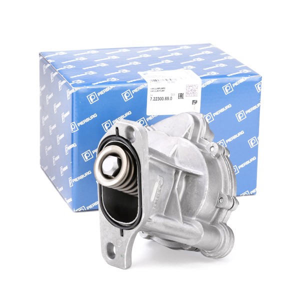
| Part Description | Brand | Part Number(s) | Price | LINK |
| Brake vacuum pump | PIERBURG | 7.22300.69.0 | £157.99 (19/01/2026) |
AUTODOC |
Vacuum pump repair kits
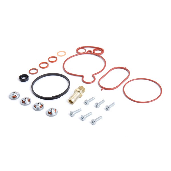
| Part Description | Brand | Part Number(s) | Price | LINK |
| Repair kit vacuum pump | DR.MOTOR AUTOMOTIVE | DRM0321 | £28.99 (19/01/2026) |
AUTODOC |
| Repair kit vacuum pump | MEAT & DORIA | 91209 | £37.99 (19/01/2026) |
AUTODOC |
| Repair kit vacuum pump | LCC | TR1416 | £21.99 (19/01/2026) |
AUTODOC |
| Repair kit vacuum pump | MAXGEAR | 27-2010 | £23.99 (19/01/2026) |
AUTODOC |
| Repair kit vacuum pump | YSPARTS | YS-VP03XLB01 | YS-VP03XLB01 (19/01/2026) |
AUTODOC |
| Repair kit vacuum pump | NTY | PVP-VW-005 | £19.99 (19/01/2026) |
AUTODOC |
| Repair kit vacuum pump | 3RG | 74704 | £32.99 (19/01/2026) |
AUTODOC |
Genuine VW brake vacuum push rod.
Usually the cause of that annoying “tap tap tap” you get on 5/6 cylinder models.
67.5mm long as opposed to the early one which is 71mm
Suits most 2.4D models from 94 (chassis number R-180 000) onwards, and all 2.5TDI models.
Also LT 6 cylinder ’94 to ’96
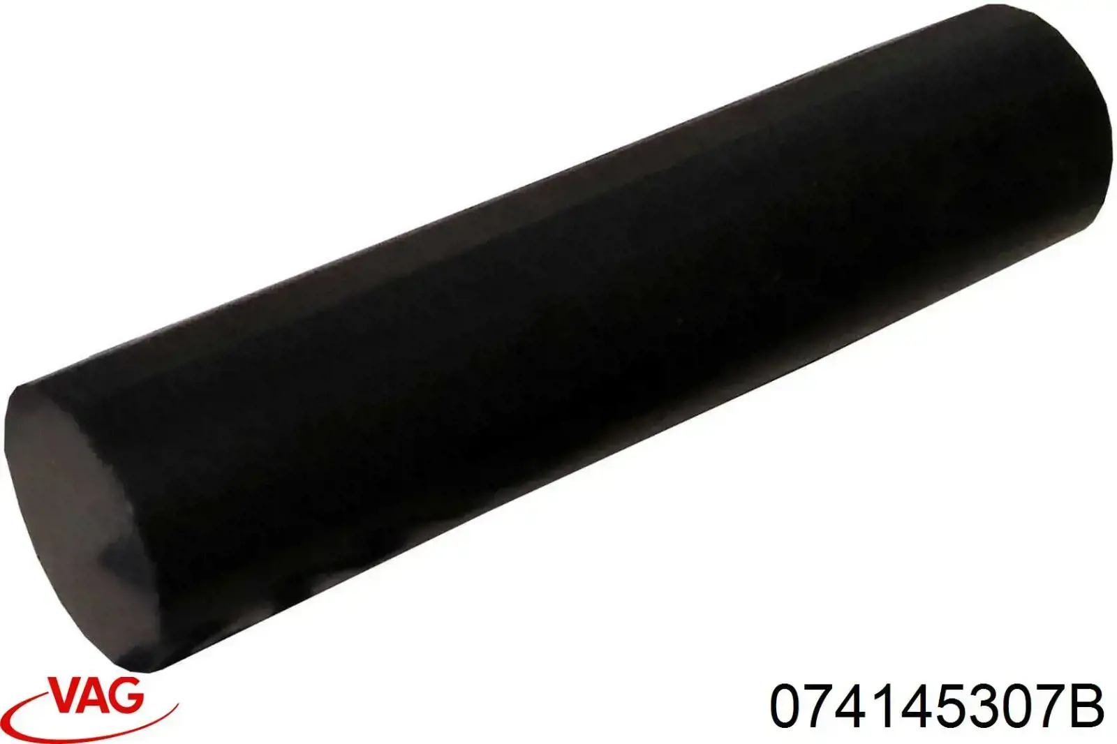
| Part Description | Brand | Part Number(s) | Price | LINK |
| Vacuum push rod | VW | 074145307B | £82.51 (19/01/2026) |
BRICKWERKS |