INFORMATION AND REPAIR
Diagnostic trouble codes (DTCs)
If the control module detects a fault, it stores a diagnostic trouble code (DTC) and the orange LEDs in the REC and the air conditioning (A/C) buttons flash for approximately 20 seconds. The control module can store up to 38 diagnostic trouble codes (DTCs). If the total diagnostic trouble codes (DTCs) exceeds 10 the five first diagnostic trouble codes (DTCs) will always be saved, while the last five become the latest diagnostic trouble code (DTCs) to be stored.
If for some reason a fault disappears after the diagnostic trouble code (DTC) has been permanently stored in the control module, information about the fault is stored in the control module.
Every diagnostic trouble code (DTC) has a counter which records the number of cycles which have been fault-free since the diagnostic trouble code (DTC) was stored (intermittent fault). A cycle is defined from when the ignition was turned on, was then on for at least 10 seconds and then turned off. Every time the cycle runs without the control module registering the fault again, increases the counter by 1. Using the counter, it is possible to determine if the control module interprets diagnostic trouble code (DTC) as permanent or intermittent. When the counter is at 0 the transmission control module (TCM) treats the fault as a permanent fault. If the counter value is greater than 0 the control module interprets this as meaning the fault is intermittent.
Diagnostic functions
 |
The Volvo on-board diagnostic (OBD) system functions are activated by pressing the REC button on the unit. The following functions are available: |
Reading and erasing diagnostic trouble codes (DTCs)
Stored diagnostic trouble codes (DTCs) can be read and erased using this service.
The on-board diagnostic (OBD) system can identify up to 10 faults, displayed as diagnostic trouble codes (DTCs). For fault-tracing, see MMB – DTC table for manual climate control unit, page 161.
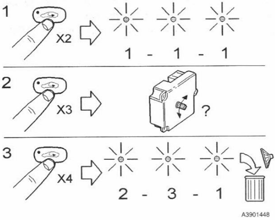
Reading Diagnostic Trouble Codes (DTCs)
-
Turn the ignition to position I or II.
-
Press the REC button twice within three seconds.
-
Note: The button must be pressed within three seconds of switching the ignition on.
-
-
Read the flashes from the REC indicator LED.
-
The REC LED flashes for 1 second, then is off for 0.5 seconds.
-
The interval between digits in a DTC code is 2 seconds.
-
The interval between different DTC codes is 5 seconds.
-
-
If the display shows 1-1-1, the control module has no stored DTCs.
Erasing Diagnostic Trouble Codes (DTCs)
-
Turn the ignition to position I or II.
-
Press the REC button four times within three seconds.
-
Note: The button must be pressed within three seconds of turning the ignition on.
-
-
After erasing the codes, perform another DTC readout to confirm that no new codes have been stored.
DTC table ECC
| Diagnostic trouble code (DTC) | Notes |
| ECC-121 | Outside temperature sensor, signal too low |
| ECC-122 | Outside temperature sensor, signal too high |
| ECC-123 | Passenger compartment temperature sensor, signal too low |
| ECC-124 | Passenger compartment temperature sensor, signal too high |
| ECC-135 | Engine coolant temperature (ECT) sensor, signal missing |
| ECC-141 | Passenger compartment temperature selector left, faulty signal |
| ECC-143 | Passenger compartment temperature selector right, faulty signal |
| ECC-211 | Damper motor position sensor temperature driver, signal too high |
| ECC-212 | Damper motor position sensor temperature driver, signal too low |
| ECC-221 | Damper motor position sensor air distribution, signal too low |
| ECC-222 | Damper motor position sensor air distribution, signal too high |
| ECC-231 | Damper motor position sensor temperature passenger, signal too high |
| ECC-232 | Damper motor position sensor temperature passenger, signal too low |
| ECC-235 | Damper motor position sensor recirculation, signal too high |
| ECC-236 | Damper motor position sensor recirculation, signal too low |
| ECC-311 | Damper motor temperature driver, faulty signal |
| ECC-312 | Damper motor temperature driver, active too long |
| ECC-313 | Damper motor temperature passenger, faulty |
| ECC-314 | Damper motor temperature passenger, active too long |
| ECC-315 | Damper motor recirculation, faulty signal |
| ECC-316 | Damper motor recirculation, active too long |
| ECC-317 | Damper motor air distribution, faulty signal |
| ECC-322 | Damper motor air distribution, active too long |
| ECC-411 | Power unit blower fan motor, faulty signal |
| ECC-412 | Fan motor passenger compartment temperature sensor, signal too low |
| ECC-413 | Fan motor passenger compartment temperature sensor, signal too high |
| ECC-414 | Fan motor passenger compartment temperature sensor, faulty signal |
| ECC-420 | ECC control module memory circuits, internal fault |
| ECC-421 | ECC control module PROM (programmable read only memory), internal fault |
| ECC-422 | Self-adjustment of damper motors temperature driver, faulty |
| ECC-423 | Self-adjustment of damper motors temperature passenger, faulty |
| ECC-424 | Self-adjustment of damper motors air distribution, faulty |
| ECC-425 | Self-adjustment of damper motors recirculation, faulty |
| ECC-431 | Blower fan speed selector switch, signal too high |
| ECC-432 | Blower fan speed selector switch, signal too low |
| ECC-433 | Blower fan motor, current too high |
| ECC-441 | Program download to control module, not carried out |
| ECC-442 | Program download to control module, faulty |
Climate Unit
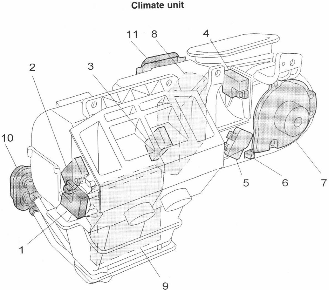
Component List
-
Damper motor – air distribution
-
Damper motor – left temperature (ECC)
-
Damper motor – right temperature (ECC)
-
Damper motor – recirculation
-
Power unit – blower fan (ECC) / Blower fan resistor (MCC)
-
Outside temperature sensor (Part No. 8702376)
-
Blower fan
-
Evaporator
-
Heater unit
-
Coolant pipe connection (to/from engine compartment)
-
Refrigerant pipe connection (to/from engine compartment)
Self-adjustment of blend door motors
The blend door motors are self-adjusting after any of them has been removed or replaced, or other work is carried out on the motor or linkage.
To activate self-adjustment, proceed as follows:
- Ignition ON, position I or II
- press in the REC button three times within three seconds.
NOTE! The control module automatically does a self-adjustment when it is connected to the car or when it registers that the power has been disconnected (e.g. battery disconnected) for more than 30 seconds.
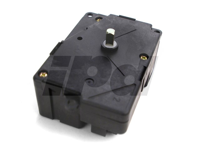
How does the blend door motor function?
The motor sends a voltage signal back to the controller between 0.5V to 4.8V.
Based on the user's desired temperature, the motor turns to a desired position based on the voltage signal back from the motor.
If the motor turns more than the voltage limits, the calibration errors out and the motor is stuck in position until a calibration is successful.
Why does my blend door motor not calibrate?
I would say there are two main reasons the motor does not calibrate.
- The motor has an internal fault such as a failed component
- The black plastic shaft which the square drive slots into has cracked. When this square hole cracks, the shaft slips inside the square hole and prevents the motor from finding the two limit points.
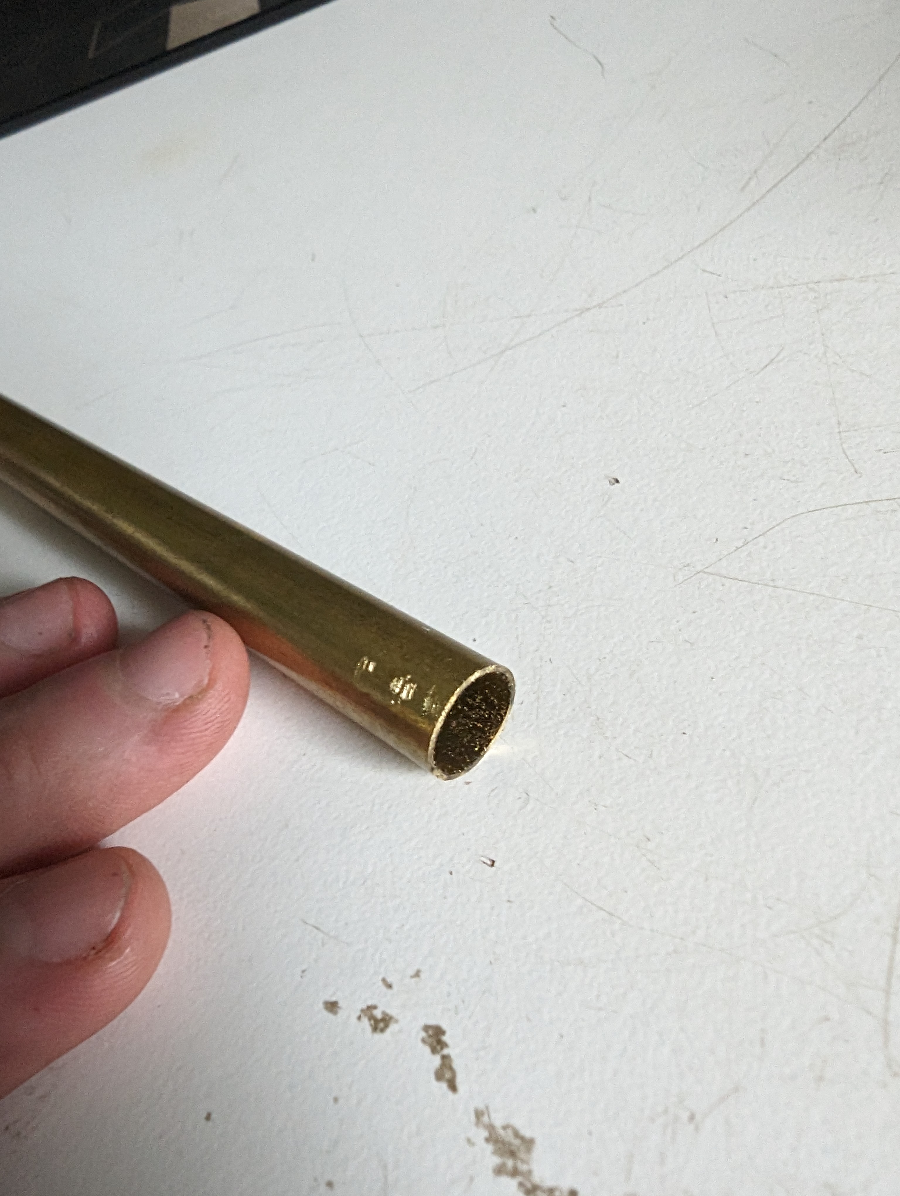
How to fix the cracked black plastic input shaft
I bought "Brass Round Tube 300mm Length 11mm OD 0.5mm Wall Thickness" I cut this into a 3mm wide piece and hammered it on the end of the rod to clamp it shut.
This prevents the square drive of the motor slipping inside the hole and lets the motor calibrate.