INJECTION PUMP ELECTRICAL TESTING
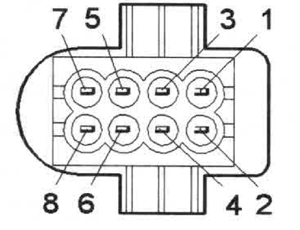
Fuel Pump Connector Terminals
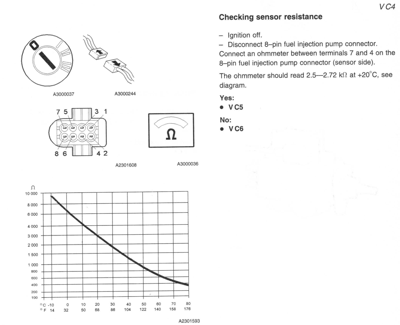
Fuel Pump Temperature Sensor
Crankshaft Seal Oil Pump Side(Front Main)
35
10
48
35
10
48
35
10
48
35
10
48
35
10
48
35
10
48
35
10
48
Fuel Pump Connector—Fuel Pump Side
| Connector | Terminal | Checking | Unit | Set Value | Min | Max | Notes |
| 8—pin Fuel injection pump | 1 — 2 | Fuel regulator position sensor | Ω | 5 | 7 | Ignition off. — Disconnect 8-pin fuel injection pump connector. Connect an ohmmeter between fuel injection pump connector terminals 1 and 2 (fuel pump (FP) side) and then between terminals 2 and 3 (fuel injection pump side). The ohmmeter should read between 5 Ohms and 7 Ohms in both cases. | |
| 8—pin Fuel injection pump | 2 — 3 | Fuel regulator position sensor | Ω | 5 | 7 | Ignition off. — Disconnect 8-pin fuel injection pump connector. Connect an ohmmeter between fuel injection pump connector terminals 1 and 2 (fuel pump (FP) side) and then between terminals 2 and 3 (fuel injection pump side). The ohmmeter should read between 5 Ohms and 7 Ohms in both cases. | |
| 8—pin Fuel injection pump | 5 — 6 | Fuel regulator | Ω | 0.5 | 2.5 | Ignition off. — Disconnect 8-pin fuel injection pump connector. Connect an ohmmeter between fuel injection pump connector terminals 5 and 6 (fuel pump (FP) side). The ohmmeter should read between 0.5 Ohms and 2.5 Ohms in both cases. | |
| 8—pin Fuel injection pump | 7—4 | Fuel temperature sensor | kΩ | 2.5 | 2.75 | Ignition off.— Disconnect 8-pin fuel injection pump connector. Connect an ohmmeter between terminals 7 and 4 on the 8-pin fuel injection pump connector (sensor side). The ohmmeter should read 2.5—2.72 kΩ at +20°C, see diagram. | |
| 8—pin Fuel injection pump | 1—Ground | Fuel shut off solenoid | Ω | 6.9 | 7.9 | Resistance in winding between terminals 1—ground: 6.9—7.9 Ω |
Fuel Pump Connector—ECU Side
| Connector | Terminal | Checking | Unit | Set Value | Min | Max | Ignition | Main Relay | Notes |
| 3—pin Fuel injection pump | 1—Ground | Signal Cable | V | <
2 |
2 | ON | ON | With ignition on, main relay on and the 3—pin fuel injection pump connector disconnected, the voltage between the 3-pin fuel injection pump connector terminal 1 (engine control module (ECM) side) and ground should be less than. 2 V. | |
| 3—pin Fuel injection pump | 2—Ground | Signal Cable | Ohms | >20 | 20 | OFF | OFF | With ignition off, main relay off (this may take up to 6 minutes) and 3-pin fuel injection pump connector disconnected, the resistance between the 3—pin fuel injection pump connector terminal 2 and ground should be greater than 20 Ohms, otherwise there is a short-circuit to ground in the cable. | |
| 3—pin Fuel injection pump | 3—Ground | Power Cable | V | Batt Voltage | Batt Voltage | Batt Voltage | ON | ON | Ignition on— Wait until the main relay is activated. Connect a voltmeter between 3-pin fuel injection pump connector terminal 3 and ground. The voltmeter should read battery voltage. |
| 3—pin Fuel injection pump | 3—3 Main Relay | Power Cable | Ohms | 0 | 0 | 0 | N/A | N/A | Check circuit between 3-pin fuel injection pump connector terminal 3 and main relay terminal 3 for an intermittent open-circuit |
| 8—pin Fuel injection pump | 1—Ground | Power Cable | V | >1.5—<3.5 | 1.5 | 3.5 | ON | ON | With the ignition on, the main relay activated and the 8—pin fuel injection pump connector disconnected, the voltage between the 8—pin fuel injection pump connector terminal 1 (engine control module (ECM) side) and ground should be between 1.5 and 3.5 V. |
| 8—pin Fuel injection pump | 2—Ground | Signal Cable | V | >4—<6 | 4 | 6 | ON | ON | With the ignition on, the main relay activated and the 8—pin fuel injection pump connector disconnected, the voltage between the 8-pin fuel injection pump connector terminal 2 (engine control module (ECM) side) and ground should be between 4.0 and 6.0 V. |
| 8—pin Fuel injection pump | 3—Ground | Power Cable | V | >0.5—<4.5 | 0.5 | 4.5 | ON | ON | With the ignition on, the main relay activated and the 8—pin fuel injection pump connector disconnected, the voltage between the 8—pin fuel injection pump connector terminal 3 (engine control module (ECM) side) and ground should be between 0.5 and 4.5 V. |
| 8—pin Fuel injection pump | 4—Ground | Ground Lead | Ohms | 0 | 0 | 0 | OFF | OFF | With the ignition off, main relay off and the fuel temperature sensor connector disconnected, the resistance between the fuel temperature sensor connector terminal 4 (engine control module (ECM) side) and ground should be approx. 0 Ohms. |
| 8—pin Fuel injection pump | 5—Ground | Power Cable | V | Batt Voltage | Batt Voltage | Batt Voltage | ON | ON | Ignition on and main relay on. Disconnect 8—-pin fuel injection pump connector. Connect a voltmeter between fuel injection pump connector terminal 5 and ground. The voltmeter should read battery voltage. |
| 8—pin Fuel injection pump | 6—Ground | Signal Cable | V | >1 | >1 | ON | ON | With the ignition on and the 8-pin fuel injection pump connector disconnected the voltage between the 8—pin fuel injection pump connector terminal 6 (engine control module (ECM) side) and ground should be greater than 1 V. Otherwise there is an open-circuit or short-circuit to ground in the cable. | |
| 8—pin Fuel injection pump | 7—Ground | Signal Cable | V | 5 | ON | ON | With the ignition on and the 8-pin fuel injection pump connector disconnected, the voltage between the 8—pin fuel injection pump connector terminal 7 (engine control module (ECM) side) and ground should be approx. 5 V. |
ECU Terminals
| Terminal | Signal Type | Ignition on | Engine idling | Miscellaneous | Scrolling value VST |
| #A1 | Power supply, fuel regulator position sensor (Sensor in injection pump) |
U=2.5 V UAC=0.4—0.5 V |
U=2.5 V UAC=0.6 V |
U increases with quantity of fuel injected | |
| #A2 | Signal ground, boost pressure sensor | Ulow | Ulow | ||
| #A3 | Signal, intake air temperature (IAT) sensor (Sensor in mass air flow(MAF) sensor) (Measuered relative to #A18) |
+10C: U=4.1V +30C: U=3.3V +50C: U=2.5V +80C: U=2.5V +100C: U=1.0V |
U decreases with increasing intake air temperature (IAT) | ||
| #A4 | Signal , needle lift sensor (Measured relative to #A18) |
U=0.2V | U increases with air mass | ||
| #A5 | |||||
| #A6 | |||||
| #A7 | |||||
| #A8 | |||||
| #A9 | |||||
| #A10 | |||||
| #A11 | |||||
| #A12 | |||||
| #A13 | |||||
| #A14 | |||||
| #A15 | |||||
| #A16 | |||||
| #A17 | |||||
| #A18 | |||||
| #A19 | |||||
| #A20 | |||||
| #A21 | |||||
| #A22 | |||||
| #A23 | |||||
| #A24 | |||||
| #A25 | |||||
| #A26 | |||||
| #A27 | |||||
| #A28 | |||||
| #A29 | |||||
| #A30 | |||||
| #A31 | |||||
| #A32 | |||||
| #A33 | |||||
| #A34 | |||||
| #A35 | |||||
| #A36 | |||||
| #A37 | |||||
| #A38 | |||||
| #A39 | |||||
| #A40 | |||||
| #A41 | |||||
| #A42 | |||||
| #A43 | |||||
| #B1 | |||||
| #B2 | |||||
| #B3 | |||||
| #B4 | |||||
| #B5 | |||||
| #B6 | |||||
| #B7 | |||||
| #B8 | |||||
| #B9 | |||||
| #B10 | |||||
| #B11 | |||||
| #B12 | |||||
| #B13 | |||||
| #B14 | |||||
| #B15 | |||||
| #B16 | |||||
| #B17 | |||||
| #B18 | |||||
| #B19 | |||||
| #B20 | |||||
| #B21 | |||||
| #B22 | |||||
| #B23 | |||||
| #B24 | |||||
| #B25 | |||||
| #B26 | |||||
| #B27 | |||||
| #B28 | |||||
| #B29 | |||||
| #B30 | |||||
| #B31 | |||||
| #B32 | |||||
| #B33 | |||||
| #B34 | |||||
| #B35 | |||||
| #B36 | |||||
| #B37 | |||||
| #B38 | |||||
| #B39 | |||||
| #B40 | |||||
| #B41 | |||||
| #B42 | |||||
| #B43 | |||||