INJECTION PUMP ELECTRICAL TESTING
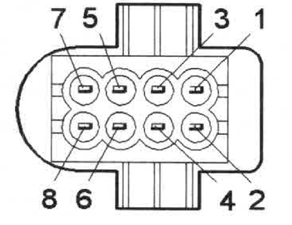
Fuel Pump Connector Terminals
Fuel Pump Temperature Sensor
Fuel Pump Connector—Fuel Pump Side
| Connector | Terminal | Checking | Unit | Set Value | Min | Max | Notes |
| 8—pin Fuel injection pump | 1 — 2 | Fuel regulator position sensor | Ω | 5 | 7 | Ignition off. — Disconnect 8-pin fuel injection pump connector. Connect an ohmmeter between fuel injection pump connector terminals 1 and 2 (fuel pump (FP) side) and then between terminals 2 and 3 (fuel injection pump side). The ohmmeter should read between 5 Ohms and 7 Ohms in both cases. | |
| 8—pin Fuel injection pump | 2 — 3 | Fuel regulator position sensor | Ω | 5 | 7 | Ignition off. — Disconnect 8-pin fuel injection pump connector. Connect an ohmmeter between fuel injection pump connector terminals 1 and 2 (fuel pump (FP) side) and then between terminals 2 and 3 (fuel injection pump side). The ohmmeter should read between 5 Ohms and 7 Ohms in both cases. | |
| 8—pin Fuel injection pump | 5 — 6 | Fuel regulator | Ω | 0.5 | 2.5 | Ignition off. — Disconnect 8-pin fuel injection pump connector. Connect an ohmmeter between fuel injection pump connector terminals 5 and 6 (fuel pump (FP) side). The ohmmeter should read between 0.5 Ohms and 2.5 Ohms in both cases. | |
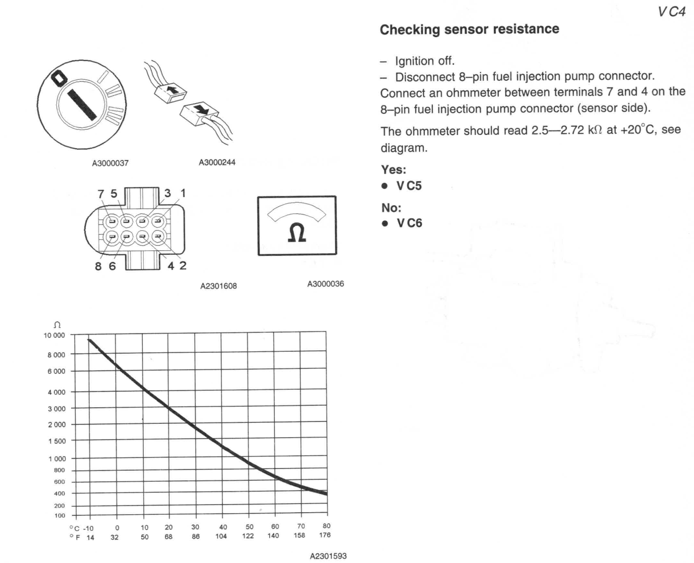
| 8—pin Fuel injection pump | 7—4 | Fuel temperature sensor | kΩ | 2.5 | 2.75 | Ignition off.— Disconnect 8-pin fuel injection pump connector. Connect an ohmmeter between terminals 7 and 4 on the 8-pin fuel injection pump connector (sensor side). The ohmmeter should read 2.5—2.72 kΩ at +20°C, see diagram. | |
| 8—pin Fuel injection pump | 1—Ground | Fuel shut off solenoid | Ω | 6.9 | 7.9 | Resistance in winding between terminals 1—ground: 6.9—7.9 Ω |
Fuel Pump Connector—ECU Side
| Connector | Terminal | Checking | Unit | Set Value | Min | Max | Ignition | Main Relay | Notes |
| 3—pin Fuel injection pump | 1—Ground | Signal Cable | V | <2 | 2 | ON | ON | With ignition on, main relay on and the 3—pin fuel injection pump connector disconnected, the voltage between the 3-pin fuel injection pump connector terminal 1 (engine control module (ECM) side) and ground should be less than. 2 V. | |
| 3—pin Fuel injection pump | 2—Ground | Signal Cable | Ohms | >20 | 20 | OFF | OFF | With ignition off, main relay off (this may take up to 6 minutes) and 3-pin fuel injection pump connector disconnected, the resistance between the 3—pin fuel injection pump connector terminal 2 and ground should be greater than 20 Ohms, otherwise there is a short-circuit to ground in the cable. | |
| 3—pin Fuel injection pump | 3—Ground | Power Cable | V | Batt Voltage | Batt Voltage | Batt Voltage | ON | ON | Ignition on— Wait until the main relay is activated. Connect a voltmeter between 3-pin fuel injection pump connector terminal 3 and ground. The voltmeter should read battery voltage. |
| 3—pin Fuel injection pump | 3—3 Main Relay | Power Cable | Ohms | 0 | 0 | 0 | N/A | N/A | Check circuit between 3-pin fuel injection pump connector terminal 3 and main relay terminal 3 for an intermittent open-circuit |
| 8—pin Fuel injection pump | 1—Ground | Power Cable | V | >1.5—<3.5 | 1.5 | 3.5 | ON | ON | With the ignition on, the main relay activated and the 8—pin fuel injection pump connector disconnected, the voltage between the 8—pin fuel injection pump connector terminal 1 (engine control module (ECM) side) and ground should be between 1.5 and 3.5 V. |
| 8—pin Fuel injection pump | 2—Ground | Signal Cable | V | >4—<6 | 4 | 6 | ON | ON | With the ignition on, the main relay activated and the 8—pin fuel injection pump connector disconnected, the voltage between the 8-pin fuel injection pump connector terminal 2 (engine control module (ECM) side) and ground should be between 4.0 and 6.0 V. |
| 8—pin Fuel injection pump | 3—Ground | Power Cable | V | >0.5—<4.5 | 0.5 | 4.5 | ON | ON | With the ignition on, the main relay activated and the 8—pin fuel injection pump connector disconnected, the voltage between the 8—pin fuel injection pump connector terminal 3 (engine control module (ECM) side) and ground should be between 0.5 and 4.5 V. |
| 8—pin Fuel injection pump | 4—Ground | Ground Lead | Ohms | 0 | 0 | 0 | OFF | OFF | With the ignition off, main relay off and the fuel temperature sensor connector disconnected, the resistance between the fuel temperature sensor connector terminal 4 (engine control module (ECM) side) and ground should be approx. 0 Ohms. |
| 8—pin Fuel injection pump | 5—Ground | Power Cable | V | Batt Voltage | Batt Voltage | Batt Voltage | ON | ON | Ignition on and main relay on. Disconnect 8—-pin fuel injection pump connector. Connect a voltmeter between fuel injection pump connector terminal 5 and ground. The voltmeter should read battery voltage. |
| 8—pin Fuel injection pump | 6—Ground | Signal Cable | V | >1 | >1 | ON | ON | With the ignition on and the 8-pin fuel injection pump connector disconnected the voltage between the 8—pin fuel injection pump connector terminal 6 (engine control module (ECM) side) and ground should be greater than 1 V. Otherwise there is an open-circuit or short-circuit to ground in the cable. | |
| 8—pin Fuel injection pump | 7—Ground | Signal Cable | V | 5 | ON | ON | With the ignition on and the 8-pin fuel injection pump connector disconnected, the voltage between the 8—pin fuel injection pump connector terminal 7 (engine control module (ECM) side) and ground should be approx. 5 V. |
ECU Terminals
| Terminal | Signal Type | Ignition on | Engine idling | Miscellaneous | Scrolling value VST |
| #A1 | Power supply, fuel regulator position sensor (Sensor in injection pump) |
U=2.5 V UAC=0.4—0.5 V |
U=2.5 V UAC=0.6 V |
U increases with quantity of fuel injected | |
| #A2 | Signal ground, boost pressure sensor | Ulow | Ulow | ||
| #A3 | Signal, intake air temperature (IAT) sensor (Sensor in mass air flow(MAF) sensor) (Measuered relative to #A18) |
+10C: U=4.1V +30C: U=3.3V +50C: U=2.5V +80C: U=2.5V +100C: U=1.0V |
U decreases with increasing intake air temperature (IAT) | ||
| #A4 | Signal , needle lift sensor (Measured relative to #A18) |
U=0.2V | U increases with air mass | ||
| #A5 | |||||
| #A6 | |||||
| #A7 | |||||
| #A8 | |||||
| #A9 | |||||
| #A10 | |||||
| #A11 | |||||
| #A12 | |||||
| #A13 | |||||
| #A14 | |||||
| #A15 | |||||
| #A16 | |||||
| #A17 | |||||
| #A18 | |||||
| #A19 | |||||
| #A20 | |||||
| #A21 | |||||
| #A22 | |||||
| #A23 | |||||
| #A24 | |||||
| #A25 | |||||
| #A26 | |||||
| #A27 | |||||
| #A28 | |||||
| #A29 | |||||
| #A30 | |||||
| #A31 | |||||
| #A32 | |||||
| #A33 | |||||
| #A34 | |||||
| #A35 | |||||
| #A36 | |||||
| #A37 | |||||
| #A38 | |||||
| #A39 | |||||
| #A40 | |||||
| #A41 | |||||
| #A42 | |||||
| #A43 | |||||
| #B1 | |||||
| #B2 | |||||
| #B3 | |||||
| #B4 | |||||
| #B5 | |||||
| #B6 | |||||
| #B7 | |||||
| #B8 | |||||
| #B9 | |||||
| #B10 | |||||
| #B11 | |||||
| #B12 | |||||
| #B13 | |||||
| #B14 | |||||
| #B15 | |||||
| #B16 | |||||
| #B17 | |||||
| #B18 | |||||
| #B19 | |||||
| #B20 | |||||
| #B21 | |||||
| #B22 | |||||
| #B23 | |||||
| #B24 | |||||
| #B25 | |||||
| #B26 | |||||
| #B27 | |||||
| #B28 | |||||
| #B29 | |||||
| #B30 | |||||
| #B31 | |||||
| #B32 | |||||
| #B33 | |||||
| #B34 | |||||
| #B35 | |||||
| #B36 | |||||
| #B37 | |||||
| #B38 | |||||
| #B39 | |||||
| #B40 | |||||
| #B41 | |||||
| #B42 | |||||
| #B43 | |||||